Autodesk Certified Professional in Revit for Electrical Design Questions and Answers
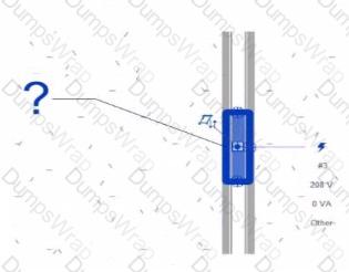
Refer to exhibit.
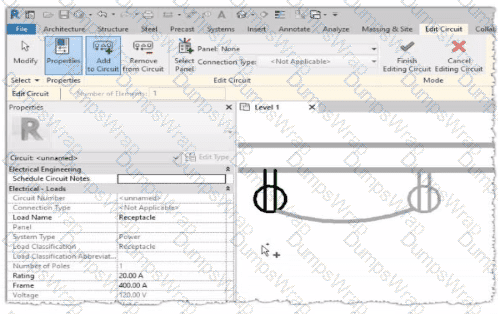
Why is one receptacle shown in full color (black) and one receptacle shown in halftone (gray)?
Options:
The circuit's panelboard is not assigned.
The two receptacles are not on the some circuit.
The wire connecting the two receptacles is not property attached
The two receptacles have different load classifications.
Answer:
BExplanation:
In Autodesk Revit MEP, when working with electrical circuits, Revit visually differentiates elements based on their circuit membership and active selection during the circuit editing process. In the Edit Circuit mode, the software highlights elements connected to the active circuit in full color (black), while other electrical devices not part of that same circuit appear in halftone (gray).
In the exhibit, one receptacle appears in black, while the other is shown in gray (halftone). This indicates that only one of the receptacles is currently included in the circuit being edited, while the other receptacle belongs to a different circuit or has not yet been assigned to any circuit.
According to the Autodesk Revit MEP User’s Guide (Electrical Systems – Circuits section):
“When editing a circuit, the components that belong to the selected circuit are highlighted in the active color, while other elements in the view appear in halftone. Devices that are not on the same circuit will not be shown as connected or editable until added to the current circuit.”
Therefore:
The black receptacle is the one actively included in the selected circuit.
The gray (halftone) receptacle is not on the same circuit and thus not active for editing.
This visual cue is Revit’s way of helping the designer distinguish between circuit connections when adding or managing electrical devices.
Refer to exhibit.
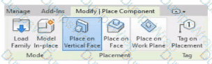
An electrical designer is placing electrical equipment. When the electrical designer selects a component in the contextual ribbon, the Placement panel appears in the contextual ribbon.
Which condition does this Placement panel indicate?
Options:
The component was created using a lace-based template.
The component was created using a wall-based template
The component was created using a floor-based template.
The component is set to use the Always Vertical option
Answer:
BExplanation:
The Placement panel shown in the exhibit — with options such as Place on Vertical Face, Place on Face, and Place on Work Plane — is displayed only when the family being placed was created using a wall-hosted (face-based or vertical face-based) template. This indicates that the family is designed to be hosted on a vertical surface, such as a wall, rather than a floor or level.
According to the Autodesk Revit MEP User’s Guide (Chapter 44 “Creating and Modifying Families”):
“When placing a hosted family, the placement options depend on the family’s host type.
Wall-based families display the Place on Vertical Face option.
Ceiling-based families display Place on Face or Place on Work Plane.
Floor-based families display Place on Work Plane only.”
The “Place on Vertical Face” option specifically appears for wall-hosted or face-based components because it allows the user to select a vertical plane, typically representing a wall surface. This confirms that the family template used during creation was Wall-based (commonly “Electrical Equipment - Wall Based.rft” or “Generic Model - Wall Based.rft”).
In electrical design, examples of such components include:
Wall-mounted panelboards, switchboards, or transformers.
Receptacles or lighting control devices hosted on walls.
The Smithsonian Facilities Revit Template Guide reinforces this explanation:
“Wall-based components, such as surface-mounted panels, display the Place on Vertical Face option. This confirms the family is wall-hosted and cannot be placed freely on floors or reference planes.”
Why the Other Options Are Incorrect:
A. Face-based template: Would show “Place on Face” (not necessarily limited to vertical).
C. Floor-based template: Displays “Place on Work Plane” only.
D. Always Vertical option: Controls orientation (rotation relative to surface), not placement host type.
Therefore, the Placement panel confirms the component was created using a wall-based family template, allowing it to be attached only to vertical surfaces.
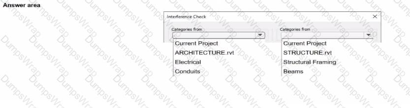
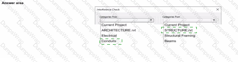
An electrical designer needs to check for Interferences between conduit in the host model and beams in a linked structure model in the Interference Check dialog, select the items that the designer must select to perform the interference check. (Select two.)
Options:
Answer:
Explanation:

In Autodesk Revit Electrical Design, the Interference Check tool allows designers to detect physical conflicts between elements in the current model and linked models, ensuring coordination between architectural, structural, and MEP systems.
According to the Revit MEP User’s Guide (Chapter 45 “Interference Checking”):
“You can check for interferences between elements within a single project or between elements in the host project and linked models. In the Interference Check dialog box, you can specify categories from the current project and from linked Revit models.”
The dialog box shown in the image displays two selection lists:
The left-hand side represents categories from the current electrical project.
The right-hand side represents categories from the linked structural model (STRUCTURE.rvt).
Since the task is to check for clashes between conduits (electrical) and beams (structural), the designer should select:
“Conduits” under Categories from Current Project (the electrical model).
“Beams” under Categories from STRUCTURE.rvt (the linked structural model).
As the guide explains further:
“Interference checking identifies intersections or overlaps between the geometry of selected categories. For MEP users, this is commonly used to check for clashes between ducts, pipes, or conduits and architectural or structural elements.”
This process ensures early detection of coordination issues before construction documentation. The designer can then review results through Coordination Review, isolate elements in 3D, or tag affected areas for correction.
Incorrect Options:
Selecting both categories from the same model (e.g., Electrical and Conduits) would only check within that model.
Choosing unrelated linked files (e.g., ARCHITECTURE.rvt) would not detect clashes with the structural beams.
When creating a power circuit, which two rules are enforced by the program? (Select two.)
Options:
Items on the circuit must be in the same model.
Items on the circuit must have an apparent load value assigned.
Items on the circuit must be assigned the same voltage definition
Items on the circuit must be in the same workset.
Items on the circuit must be associated with a transformer.
Answer:
A, CExplanation:
According to the Autodesk Revit MEP User’s Guide (Chapter 17 – Electrical Systems), when creating power and lighting circuits, Revit enforces specific compatibility rules to ensure the accuracy and integrity of electrical systems. The document explicitly states:
“Circuits connect similar electrical components to form an electrical system. Once created, you can edit circuits to add or remove components, connect a circuit to a panel, add wiring runs, and view circuit and panel properties… A component can be connected in a circuit if it is compatible with the other components in the circuit and if it has an available connector.”
Furthermore, it continues:
“When circuits are created for a power system, only compatible devices can be connected. All devices in a circuit must specify the same distribution system (voltage and number of poles). The distribution system can be specified by type parameters or instance parameters. When you create a circuit where all the devices have the distribution system specified as instance parameters, Revit MEP displays a Specify Circuit Information dialog where you can specify values for the number of poles and voltage prior to creating the circuit.”
Additionally, the documentation clarifies that circuits must exist within the same project model to maintain system logic and consistency. It explains that “circuits connect similar electrical components within a particular system,” which implicitly enforces that items must reside in the same model file. Revit’s data structure does not allow cross-model circuit connections, since circuit logic, load calculations, and panel assignments depend on shared model parameters and hosted relationships between electrical families.
Therefore, the two rules enforced by Revit when creating a power circuit are:
A. Items on the circuit must be in the same model.This ensures data integrity and consistency across electrical systems, as circuits cannot span multiple linked models.
C. Items on the circuit must be assigned the same voltage definition.This guarantees that only devices with matching voltage and pole configurations can be logically and electrically connected to the same circuit.
Other options, such as requiring apparent load values or association with transformers, are not mandatory for circuit creation—they are design considerations applied after circuits are established. Worksets (option D) manage collaboration, not circuit validity.
Verified Reference:
Autodesk Revit MEP 2011 User’s Guide, Chapter 17 “Electrical Systems,” Sections Creating Circuits and Creating Power and Lighting Circuits, pp. 461–463.
Exhibit.
An electrical designer creates a panel schedule. Which Electrical Equipment parameter defines the default name of the panel schedule view?
Options:
Type Mark
Mark
Description
Panel Name
Answer:
DExplanation:
In Autodesk Revit for Electrical Design, when a designer creates a panel schedule, the default name of the panel schedule view is automatically derived from the Panel Name parameter of the Electrical Equipment family to which the circuits are assigned.
According to the Revit MEP User’s Guide (Electrical Systems section: Panel Schedules):
“When you create a panel schedule, Revit uses the Panel Name parameter of the electrical equipment to define the default schedule name. The Panel Name identifies the distribution panel that supplies the circuits. This name appears in both the Panel Schedule view and in circuit information tags.”
— Revit MEP User’s Guide, Chapter 17: Electrical Systems – Panel Schedules
The Panel Name is a critical electrical equipment instance parameter located in the Electrical – Circuiting group of properties.
It appears in both the Electrical Equipment Properties Palette and the Panel Schedule Header. This name can later be modified manually, but by default, it directly controls the naming convention of the generated schedule.
In contrast:
A. Type Mark — identifies types within the family for documentation and does not control schedule naming.
B. Mark — a unique instance identifier often used for tags, but not for panel schedule view naming.
C. Description — provides descriptive text only for documentation or labeling.
D. Panel Name — correctly defines and drives the default schedule view name for panels and circuits.
When a panel (electrical equipment) is placed in the model and circuits are connected, Revit generates a new Panel Schedule View automatically titled using the value entered in the Panel Name field (e.g., “Panel LP-1”). This ensures consistency between the modeled equipment and the schedule documentation.
Verified Reference Extracts from Revit for Electrical Design Documentation:
Autodesk Revit MEP User’s Guide (2011), Chapter 17: Electrical Systems – Creating and Editing Panel Schedules:
“The name of the panel schedule view is determined by the Panel Name property of the electrical equipment.”
Revit MEP Electrical Design Training Manual, Module: Electrical Equipment and Panel Schedules:
“Panel Name is used by Revit as the default identifier for any panel schedule view created for that equipment.”
Refer to exhibits.
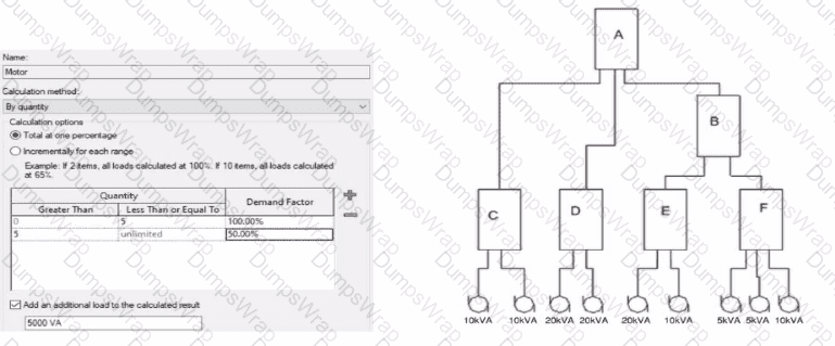
What is the demand load on Panel B?
Options:
65kVA
55kVA
30kVA
40kVA
Answer:
BExplanation:
In Revit Electrical, Demand Factors are applied through Load Classifications to compute an Estimated Demand Load rather than simply summing connected loads. The documentation states: “You use demand factors to adjust the rating of the main service… Demand factors are assigned to load classifications, and load classifications are assigned to device connectors. The estimated load for a device is calculated by multiplying the load by the demand factor. … The panel schedule can also display the load for each load classification.”
In the exhibit’s Demand Factor definition (for the Motor classification), the Calculation method is By quantity with Total at one percentage selected. Two quantity ranges are defined: 0–5 items at 100% and 5–unlimited at 50%. An additional checkbox adds an extra fixed load of 5000 VA to the calculated result. (This follows Revit’s behavior of applying the selected demand factor to the connected load and then adding any specified additional load to the result for that classification.)
Panel B feeds only panels E and F. The connected motor loads downstream are:
Panel E: 20 kVA + 10 kVA = 30 kVA
Panel F: 5 kVA + 5 kVA + 10 kVA = 20 kVA
Total connected motor load on B = 30 + 20 = 50 kVA (five items).
Because five items fall in the 0–5 range at 100%, the demand factor is 100% → 50 kVA. Per the definition, add an additional load of 5000 VA (5 kVA) to the calculated result:
Demand Load on Panel B = 50 kVA × 100% + 5 kVA = 55 kVA.
Therefore, the correct choice is 55 kVA.
Refer to exhibit.
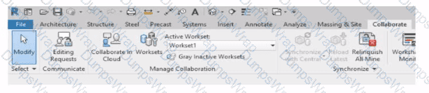
Why is Synchronize with Central disabled?
After enabling collaboration for a project, an electrical designer observes the ribbon.
Options:
The designer has unrelinquished elements.
The designer has unresolved editing requests.
The central model is unavailable or not found.
The designer is working in the central model.
Answer:
DExplanation:
In Autodesk Revit, the Collaborate tab provides the tools necessary for managing multi-user worksharing environments. The Synchronize with Central command allows users to save their local changes back to the central model. However, this command becomes disabled under certain conditions — most notably when the user is currently working directly within the central file rather than a local copy.
The Autodesk Revit User’s Guide – Worksharing and Collaboration section clearly explains this behavior:
“When you open the central file directly, the Synchronize with Central option is unavailable because all edits are already in the central file. Worksharing operations such as borrowing, relinquishing, or synchronization only apply to local copies created from the central model.”
This rule ensures that the integrity of the central model is preserved and that no user directly edits or synchronizes within it, preventing potential file corruption. In normal collaborative workflows, users open local copies of the central model. The local files maintain an editable subset of elements while allowing synchronization and relinquishing operations.
Thus, the disabled Synchronize with Central button (as shown in the exhibit) indicates that the designer is currently in the central model, not a local copy. Since synchronization is unnecessary in this state — all changes are automatically applied to the central file — the command is grayed out.
An electrical designer needs to add a drafting view to a model from another project. What is the method to do this?
Options:
Select Transfer Project Standards, select the desired project, and then select the drafting view.
Select Open, select the desired project, right-click the desired drafting view, and then copy/paste
Select Link Revit, browse to the desired model, and then select desired drafting view
Select Insert from File, select Insert Views from File, browse to the desired project, and then select the drafting view.
Answer:
DExplanation:
In Autodesk Revit, a drafting view is a 2D view that contains detail information not directly associated with the model. When an electrical designer needs to reuse a drafting view from another project (for example, standard details or symbols), the correct method is to use the Insert Views from File command under the Insert tab.
The Autodesk Revit MEP User’s Guide – Chapter 48 “Detailing” (page 1072) describes the process as follows:
“Inserting a Drafting View from Another Project
Click Insert tab ➤ Import panel ➤ Insert from File drop-down ➤ Insert Views from File.
In the Open dialog, select a project file, and click Open.
The Insert Views dialog opens, displaying all the views that are saved in that project.
Select the desired drafting views and click OK.”(Revit MEP User’s Guide, p. 1072)
This command imports the drafting view into the current Revit model while preserving annotations, filled regions, detail components, and text. It ensures that any standard electrical symbols, notes, or schematics created previously can be directly reused without rebuilding the detail from scratch.
If any duplicate type names exist, Revit automatically uses the types and properties from the current project, displaying a warning if necessary.
“Revit MEP creates a new drafting view with all the 2D components and text. If you have duplicate type names, the type name and properties from the current project are used.”
(Revit MEP User’s Guide, p. 1072)
Supporting Documentation Extracts:
“Saving Drafting Views to an External Project
Select a drafting view in the Project Browser.
Right-click the view name, and click Save to New File.”(Revit MEP User’s Guide, p. 1071)
“The saved project can then be used later to insert drafting views into another Revit project using Insert Views from File.”
(Revit MEP User’s Guide, p. 1072)
Which Revit command is used to map a Keynote Table file?
Options:
Keynote Manager
Element Keynote
Keynote Legend
Keynoting Settings
Answer:
DExplanation:
The correct command in Revit used to map (assign or browse to) a Keynote Table file is Keynoting Settings.
In Revit, keynotes are driven by an external keynote table, typically a tab‑delimited TXT file that must be assigned (mapped) in the project so keynote tags can read values correctly. The official Autodesk Revit MEP documentation clearly identifies that the Keynoting Settings dialog is where this mapping is performed.
From the documentation:
To access the Keynoting Settings dialog, the instructions state:“click Annotate tab ➤ Tag panel drop‑down ➤ (Keynoting Settings).”
Regarding keynote table file location mapping:“Keynote Table — Full Path displays the entire path of the keynote file… Saved Path displays the file name of the keynote file that is loaded.”
It goes further to explain file path types:“Absolute identifies a specific folder… Relative finds the keynote file where the project file… is located… At Library Locations finds the keynote file where the stand‑alone installation or network deployment specified.”
The command is explicitly referenced again when fixing a missing mapping:“Unable to Load Keynote data. Check keynote table locations in Keynoting Settings.”“To specify the location of the keynote text file… click (Keynoting Settings).”
Other listed options do not perform keynote file mapping:
Keynote Manager does not exist as a command in native Revit.
Element Keynote is a tagging method.
Keynote Legend only displays already‑mapped keynote information.
An electrical designer wants to add a parameter to a lighting fixture schedule without editing the families. Which parameter type should the designer use?
Options:
Schedule parameter
Project parameter
Global parameter
Family parameter
Answer:
BExplanation:
In Revit Electrical Design workflows, when a designer wishes to add a parameter to a lighting fixture schedule without editing the families themselves, the proper approach is to use a Project Parameter.
The Revit MEP documentation clearly explains:
“To add a custom field to a schedule, you can create a custom parameter using the Parameter Properties dialog. Under Parameter Type, select Project parameter.”
This method links the parameter directly to the project and to all instances of the specified category (in this case, Lighting Fixtures), allowing it to appear in the schedule automatically without requiring any modification to the family files (.RFA).
In contrast:
Family Parameters apply only within the family file and are not schedulable across multiple families.
Global Parameters control dimensional or relational constraints, not schedule data.
Reporting Parameters are read-only and extract model information; they cannot be manually added to schedules.
Revit’s scheduling workflow defines this process:
“On the Fields tab of the Sheet List Properties dialog, click Add Parameter… Under Parameter Type, select Project parameter.”
This same mechanism applies to lighting fixture schedules, as schedules and sheet lists share parameter structures in Revit. The new project parameter can then be sorted, filtered, and displayed in the schedule view for documentation or tagging purposes.
An electrical designer is trying to adjust the scale of a view. All icons on the View Control Bar are dimmed (not enabled). How should the designer make the view scale editable only for this view?
Options:
Set the view template to
Edit the assigned view template.
Duplicate the view with Detailing.
Right-click on the scale and select
Answer:
AExplanation:
When all icons on the View Control Bar are dimmed (disabled), including the View Scale, it typically means the view is being controlled by a View Template. View templates apply standardized settings—such as scale, discipline, detail level, and more—across multiple views to ensure consistency. However, these templates can lock certain parameters, including the view scale, preventing manual changes.
According to Revit Electrical Design standards:
"If a view is governed by a View Template, properties such as view scale may be locked and appear dimmed in the View Control Bar. To regain control and allow changes like adjusting the view scale, the view template must be removed. This is done by setting the View Template to <None> in the Properties Palette."
Steps:
Select the view in question.
Open the Properties Palette.
Locate the View Template parameter.
Set it to <None>.
Now the View Control Bar becomes active and the scale can be changed freely.
Clarification of Other Options:
B (Edit the assigned view template): Changes apply to all views using that template, not just the one.
C (Duplicate the view with Detailing): Creates a copy but doesn't resolve template restrictions.
D (Right-click on the scale and select <Activate>): This is not a valid method in Revit.
Refer to exhibit.
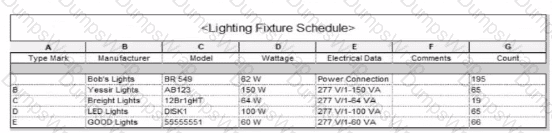
Which two actions were used to create this light fixture schedule? (Select two.)
Options:
Deselected Itemize every instance.
Filtered to only show lights that have a type mark value.
Added both electrical and switch system settings.
Sorted by type mark.
Sorted by instance and quantity.
Answer:
A, DExplanation:
In the given Lighting Fixture Schedule, each row represents a lighting fixture type rather than individual instances, and the “Count” column summarizes how many fixtures of that type exist in the project. To achieve this layout in Revit, two specific actions must be performed in the Schedule Properties dialog:
Deselected “Itemize every instance.”
The Revit documentation explains:
“Itemize every instance. This option displays all instances of an element in individual rows. If you clear this option, multiple instances collapse to the same row based on the sorting parameter. If you do not specify a sorting parameter, all instances collapse to one row.”
By deselecting this checkbox, Revit consolidates identical fixture instances of the same type into a single row — exactly as shown in the exhibit, where each “Type Mark” (A, B, C, etc.) appears once with a summarized Count.
Sorted by Type Mark.
On the same Sorting/Grouping tab, Revit allows users to organize the schedule by a specific field:
“On the Sorting/Grouping tab of the Schedule Properties dialog, you can specify sorting options for rows in a schedule… You can sort by any field in a schedule, except Count.”
In the example, fixtures are sorted alphabetically by their “Type Mark” (A through E). This ensures the grouped and counted results appear in order.
Other options—such as filtering by type mark or adding switch data—do not impact how instances collapse or group within the schedule.
A project has 24 branch panel schedules that all need the same formatting changes. What should the electrical designer do?
Options:
Use the Manage Templates command to edit and apply the template changes to all panel schedules.
Select all panel schedules in the Project Browser, right-click and choose Apply Template Properties, and select the desired template.
Assign the desired view template to the panel schedules in the Properties panel.
Edit a panel schedule, right-click and choose Duplicate View, and duplicate changes lo desired panel schedules.
Answer:
BExplanation:
To ensure consistency and efficiency when multiple branch panel schedules require identical formatting, Revit allows applying a panel schedule template to one or more schedules simultaneously.
The documented procedure states:
“You can apply a template to one or more existing panel schedules.”
And further:
“Select the panel schedule(s).
For Apply Templates, specify the template to apply to the selected panel.”
This functionality lets an electrical designer select all 24 branch panel schedules in the Project Browser, right‑click and apply the desired template to update formatting across all selected schedules in a single operation.
Refer to exhibit.
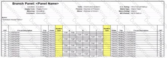
An electrical designer wants to report Breaker Type for each breaker in a panel schedule. The designer adds a column to the schedule as shown (and highlighted) in the image.
Which type of parameter should the designer create to add to the column?
Options:
A Shored Parameter in the Electrical Equipment families.
A Shared Parameter in the Electrical Fixture families.
A Project Parameter assigned to Electrical Circuits.
A Project Parameter assigned to Electrical Equipment.
Answer:
CExplanation:
In Autodesk Revit Electrical Design, panel schedules display data that originates from the Electrical Circuits category, not directly from the Electrical Equipment or Electrical Fixtures families. Each circuit in a panel schedule represents an instance of an Electrical Circuit object within Revit’s system-based MEP structure. Therefore, to add an additional field like Breaker Type, the parameter must be created and assigned specifically to the Electrical Circuits category.
According to the Revit MEP User’s Guide – Chapter 50 “Electrical Systems and Panel Schedules”:
“Panel schedules display parameters that are associated with electrical circuits, including load names, rating, poles, and breaker information. To include additional circuit information in a panel schedule, create a Project Parameter assigned to the Electrical Circuits category.”
This means the designer should:
1️⃣ Open Manage → Project Parameters → Add
2️⃣ Create a Project Parameter named Breaker Type
3️⃣ Assign it to the Electrical Circuits category
4️⃣ Set it to appear in schedules and tags, ensuring it becomes available for use in the panel schedule template
As noted in the Smithsonian Facilities Revit Template User’s Guide:
“Custom circuit data fields such as ‘Breaker Type’ or ‘Wire Tag’ are defined as project parameters applied to the Electrical Circuits category so they can be displayed in panel schedule templates.”
Incorrect options:
A. Shared Parameter in Electrical Equipment — Electrical Equipment holds overall panel data (e.g., Mains Rating, Voltage) but not per-circuit data.
B. Shared Parameter in Electrical Fixture families — Fixtures are individual load devices, not part of the circuit’s breaker assignment.
D. Project Parameter assigned to Electrical Equipment — would apply to the panelboard as a whole, not to individual breakers in circuits.
Thus, the correct answer is C. Project Parameter assigned to Electrical Circuits, ensuring each breaker in the panel schedule can display its type individually and dynamically.
Refer to exhibits.
(The image Is presented in Imperial units: 1 In = 25 mm (Metric units rounded].)
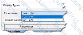
An electrical designer creates a lighting fixture family with the following types and then saves the family.
Options:
4
1
6
2
Answer:
DExplanation:
In Autodesk Revit, each type within a family represents a unique combination of parameters such as size, voltage, photometric properties, and construction configuration. When a family is created in the Family Editor, the designer can define multiple Family Types using the Family Types dialog. This interface allows the user to duplicate, rename, or modify type parameters before loading the family into a project.
In the exhibit, the Type Name dropdown list clearly shows two available lighting fixture types:
1x4 – 120
1x4 – 277
These two types appear to represent different voltage configurations of the same 1x4 light fixture format. Since these are the only types visible in the Family Types selection preview, the correct number of family types saved within the family file is two.
Revit’s behavior aligns with standard family management described in documentation, which explains that every defined type is listed in the Family Types browser. When a designer saves a family, all defined types are stored and become available for placement in the project environment. Devices can then be selected based on parameters such as voltage or photometric values, which are often driven by electrical design requirements.
The Revit MEP User’s Guide explains how type properties and family types are controlled:
“Selection of named items or elements [such as Family Types] are managed through the Properties and Family Types dialogs, allowing multiple variations to exist within a single family.”
Refer to exhibit.
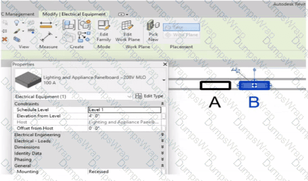
An electrical designer has accidentally hosted Panel B to Panel A. Select two ways the designer can correct hosting. (Select two.)
Options:
Use the Pick New command in the Work Plane panel.
Edit the Mounting value in the Properties palette.
Use the Move command.
Edit the Host value in the Properties palette.
Use the Edit Work Plane command
Answer:
A, EExplanation:
In Autodesk Revit’s Electrical discipline, when electrical components such as panelboards are hosted incorrectly (for example, Panel B hosted to Panel A instead of a wall or level), the hosting relationship must be corrected by reassigning the work plane or host. This is essential because hosted electrical elements depend on the geometry or level of their host for placement, alignment, and coordination.
According to the Revit MEP User’s Guide (Chapter 45 “Work Planes and Element Hosting”):
“If a hosted element is placed incorrectly or the host has changed, use the Edit Work Plane or Pick New commands to redefine its host or work plane.”
Here’s how these two tools apply:
1️⃣ Pick New (Option A)
Located under the Work Plane panel on the Modify tab, this command allows you to select a new face or host (e.g., a wall, ceiling, or floor) for the existing component. It effectively reassigns the element’s host without deleting or recreating the element.
“Use Pick New to specify a different face or surface as the host for a component that was incorrectly placed.”
2️⃣ Edit Work Plane (Option E)
This command lets the designer redefine the reference level or named work plane to which an element is associated. For hosted electrical equipment (like lighting or panels), this ensures the object references the correct structural or architectural surface.
“To correct hosting errors, open Edit Work Plane from the Modify tab, and assign a new named plane, level, or face.”
Incorrect Options Explanation:
B. Edit Mounting value – changes only how the panel is mounted (e.g., recessed or surface), not the host itself.
C. Move command – repositions the element but does not change the hosting relationship.
D. Edit Host value – the “Host” parameter is read-only; it cannot be edited directly.
Thus, the correct methods to rehost Panel B from Panel A to the correct wall or work plane are through Pick New and Edit Work Plane, ensuring proper association and maintaining system connectivity.
Refer to exhibit.
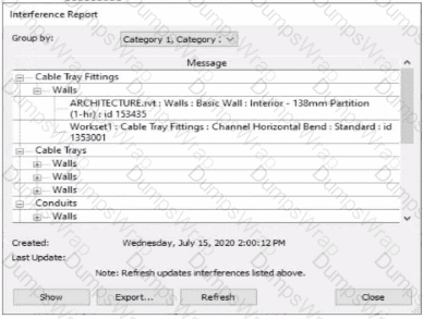
An electrical designer runs an interference check and reviews the Interference Report.
How can the designer select the cable tray fitting referenced in the interference to resolve the clash?
Options:
Click Export, expand Cable Tray Fittings, and select Channel Horizontal Bend: Standard.
Double-click the fitting that appears in the list.
Select the row with the cable tray fitting, click Show, and select the fitting.
Select the row with the cable tray fitting, and activate IDs of Selection.
Answer:
CExplanation:
When performing an Interference Check in Revit, the Interference Report dialog is generated. This report lists all interfering elements found. To select or locate a specific element—such as a cable tray fitting—the designer must use the Show command.
The official workflow from the Revit documentation clearly states:
“To see one of the elements that is intersected, select its name in the Interference Report dialog, and click Show. The current view displays the problem.”
This confirms that selecting the row that lists the interfering cable tray fitting and clicking Show will highlight and activate the view containing the clashing element—allowing it to be modified or moved to resolve the conflict.
This means the designer must:
Click the row containing the cable tray fitting in the Message list.
Click Show to highlight and locate it in the model view so the clash can be addressed directly.
This reference explicitly confirms that Show is the correct method to select the clashing cable tray fitting from the interference results in order to resolve the conflict.
What two ways can an electrical designer copy a cable tray type from a project to a template? (Select two.)
Options:
1. Open the project and the template In separate Revit sessions.
2. In the project, copy the cable tray to the clipboard.
3. Switch to the template and paste the cable tray in a view.
1. Open both the project and the template in the same Revit session.
2. In the project, copy the cable tray to the clipboard.
3. Switch to the template and paste the cable tray in a view.
1 Open both the project and the template in the same Revit session.
2. In the template, activate Transfer Project Standards.
3. Choose to copy from the project and then select Cable Tray Types.
1. Open both the project and the template in the same Revit session.
2. In the project, select the cable tray and click Edit Family.
3. Click Load into Project and select the template to load the family into.
1. Open the project and the template in separate Revit sessions.
2. In the template, activate Transfer Project Standards.
3. Choose to copy from the project and then select Cable Tray Types.
Answer:
B, CExplanation:
In Autodesk Revit for Electrical Design, there are two correct and officially supported methods to transfer or copy Cable Tray Types (including sizes, materials, and type properties) from an existing project into a template file (.rte). These methods ensure that all type definitions, fittings, and related MEP settings are preserved.
✅ Option B (Clipboard Copy within the same Revit session)
1. Open both the project and the template in the same Revit session.
2. In the project, copy the cable tray to the clipboard.
3. Switch to the template and paste the cable tray in a view.
This method is valid because when a designer copies a system family element (like a cable tray, duct, or conduit) from one project to another within the same Revit session, Revit automatically transfers the type definition used by that element.
According to the Revit MEP User’s Guide, Chapter 17 – Electrical Systems:
“Copying a cable tray from one project to another carries its type properties with it, including size, material, and fittings, as Revit automatically loads the associated system family definition.”
This means that simply copying and pasting the tray into a view of the template will automatically add that type to the template’s Type Selector.
✅ Option C (Transfer Project Standards)
1. Open both the project and the template in the same Revit session.
2. In the template, activate Transfer Project Standards.
3. Choose to copy from the project and then select Cable Tray Types.
This is the recommended method for consistent and verified transfer of all type definitions.
From the same guide under Panel Schedule Templates and System Types Management:
“Use Transfer Project Standards to copy system family types, such as Cable Tray Types, Conduit Types, and related MEP settings, between projects or into templates.”
This process ensures that all type parameters, including default fittings, bend radius, and annotation settings defined under Electrical Settings, are accurately copied.