
HCIE-Datacom-Carrier (Written) V1.0 Questions and Answers
A device receives two BGP routes for the same prefix from two peers, with one route received from each peer. One route has next hop NH1, whereas the other has next hop NH2. All other attributes of the two routes are identical. NH1 recursively resolves to two direct next hops, A and B, and NH2 likewise recursively resolves to two direct next hops, C and D. If BGP is configured with the maximum load-balancing 2 command and the device supports at most six load-balancing routes, how many load-balancing routes for the relevant prefix are present in the FIB?
Options:
4
2
3
1
Answer:
AExplanation:
Huawei Reference Verification:
Huawei's BGP multipath architecture distinguishes the number of BGP routes selected from the number of directly reachable FIB next hops produced by route recursion. The maximum load-balancing parameter controls the number of eligible equal-cost BGP paths. Each selected BGP next-hop address may recursively resolve through multiple equal-cost direct next hops. In this scenario two BGP paths are selected and each resolves through two direct forwarding alternatives. The total of four FIB next hops remains within the stated platform maximum of six. Therefore the correct answer is four.
Technical Deep Dive:
A is correct. `maximum load-balancing 2` permits two equivalent BGP paths for one destination, which here have BGP next hops NH1 and NH2. Route recursion then considers the IGP or directly connected paths that make each BGP next hop reachable. NH1 resolves to direct next hops A and B, while NH2 resolves to C and D. The installed FIB next-hop group therefore contains A, B, C and D, four choices in total. The device's six-path upper limit is a cap rather than a requirement to synthesize six routes. On Huawei carrier routers, the BGP control plane selects and resolves paths; forwarding NP/ASIC logic performs ECMP selection among the installed direct next hops. Useful diagnostic commands include `display bgp routing-table`, `display ip routing-table`, and `display fib`. The distinction between BGP multipath selection and physical recursive next-hop expansion is the key to the question.
───────────────────────────────────────────────────────
Which of the following statements are accurate about the SR Policy configuration shown?
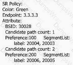
Exhibit 33.1 — Original topology/configuration figure
Select all that apply.
Options:
CP2 is the primary path of the SR Policy.
Traffic destined for 3.3.3.3 can recurse to the SR Policy.
Traffic with the next hop 3.3.3.3 can recurse to the SR Policy.
The color value is transmitted through a BGP route.
Answer:
A, C, DExplanation:
Exact Extract — Huawei Training Material (Automatic SDN Network O & M, p.19):
“SR-MPLS TE Policy is a new tunnel diversion technology developed based on SR. An SR-MPLS TE policy consists of the following three parts: Ingress, Color, and End point. Color indicates the extended community attribute carried in the SR-MPLS TE Policy. End point specifies the destination address of the SR-MPLS TE Policy.”
Huawei Reference Verification:
Huawei SR-MPLS TE Policy architecture identifies an ingress, a Color Extended Community and an endpoint. Eligible BGP VPN routes can be steered to a policy when the route's BGP next hop matches the policy endpoint and its Color Extended Community matches the policy color. Candidate paths are ordered by preference, and the highest valid preference determines the active path. In the exhibit CP2 has preference 200, while CP1 has 100, so CP2 is active. The color can be transmitted as a BGP route attribute. Traffic's destination address alone is not the matching criterion for automatic color-based recursion. Thus A, C and D are correct.
Technical Deep Dive:
A, C and D are correct. The SR Policy has Color Green, Endpoint 3.3.3.3 and Binding SID 30028. CP1 carries labels 20004 and 20003 with preference 100, whereas CP2 carries 20006 and 20005 with preference 200. CP2 wins when valid because its preference is greater. A BGP service route carrying Green as its Color Extended Community and 3.3.3.3 as its next hop can recurse to that policy. The packet's own final destination may be a customer prefix unrelated to 3.3.3.3; the routing recursion matches the BGP next hop and color. The BSID identifies the policy and abstracts its current active segment list. Huawei's forwarding plane translates the selected list into the required MPLS label operations and forwards packets accordingly. Distinguishing route next hop from packet destination avoids the incorrect answer B.
───────────────────────────────────────────────────────
The system IDs for the same IS-IS device in separate processes can be identical.
Options:
TRUE
FALSE
Answer:
AExplanation:
Huawei Reference Verification:
Huawei IS-IS multi-process operation keeps separate link-state databases, neighbor state, and route calculations for distinct routing-process instances. IS-IS system IDs must be unique among nodes within the same applicable routing domain to avoid conflicting LSP identities. However, using the same system ID in independent IS-IS processes on one router is permissible when their associated routing instances do not collide. The process number distinguishes the local protocol instance; the system ID identifies the device within the relevant IS-IS domain. Accordingly the statement is true.
Technical Deep Dive:
A is TRUE. An IS-IS NET contains an area portion, a six-byte system ID, and an N-selector, typically 00. For example, 49.0001.0000.0000.0001.00 contains system ID 0000.0000.0001. Router identities must be unique within a shared LSDB because duplicate system IDs cause LSP collisions and unstable topology representation. A device can nevertheless run multiple independent IS-IS processes with separate interfaces and databases. Reusing the system ID across those distinct processes does not inherently violate the uniqueness requirement as long as each routing domain remains unique internally. This distinction is between the globally configured value on the physical device and its meaning inside a protocol domain. On VRP, `display isis brief`, `display isis peer` and `display isis lsdb` allow engineers to check process, adjacency and LSP state.
───────────────────────────────────────────────────────
In the network shown, RT4 and RT5 function as ASBRs and import IS-IS routes into OSPF. Only OSPF is used for interworking between RT4 and RT5. The link costs are shown in the figure. The key configurations of RT4 and RT5 are as follows:
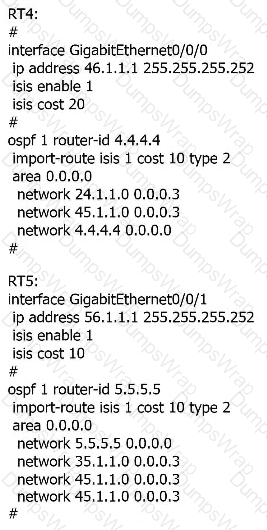
Exhibit 36.1 — Original topology/configuration figure
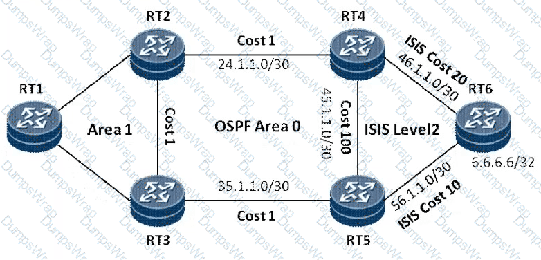
Exhibit 36.2 — Original topology/configuration figure
Options:
RT1 accesses 6.6.6.6 through the RT2 - > RT4 - > RT6 path.
RT1 has two routes to 6.6.6.6, and traffic is balanced between the two routes.
RT1 accesses 6.6.6.6 through the RT3 - > RT5 - > RT6 path.
RT1 has two routes to 6.6.6.6 and selects one of them to forward traffic.
Answer:
BExplanation:
Huawei Reference Verification:
Huawei OSPF External Type 2 route selection considers the external metric first; when E2 metrics are equal, internal cost toward the advertising ASBR serves as an additional comparison. RT4 and RT5 import the IS-IS destination as OSPF Type 2 external routes with the explicitly configured external metric of 10. The illustrated OSPF paths to RT4 and RT5 have equal internal cost from RT1. Therefore RT1 installs two equal-cost forwarding paths to 6.6.6.6. The differing IS-IS link costs to RT6 do not override the imported OSPF Type 2 metric. Thus B is correct.
Technical Deep Dive:
B is correct. RT4 and RT5 are ASBRs because they inject routes learned in IS-IS into OSPF. Both use `import-route isis 1 cost 10 type 2`. As a result the advertised E2 cost for 6.6.6.6 is 10 from either ASBR. RT1 can reach RT4 through RT2 and RT5 through RT3, and the illustrated internal OSPF costs for those alternatives are equal. The two paths therefore qualify for ECMP, unlike a single preferred next hop. The original IS-IS costs (20 on the RT4 side and 10 on RT5) are internal to the source routing domain; they are not the metric used after the explicit E2 import cost is assigned. Huawei commands `display ospf routing`, `display ospf lsdb ase` and `display ip routing-table 6.6.6.6` help confirm the route type and next hops. ASIC forwarding can distribute traffic across installed ECMP entries.
───────────────────────────────────────────────────────
In the OSPFv3 network shown, RTD imports an external route. The AS-External-LSA details are checked on RTG. Based on the following information, what should the Originating Router be?
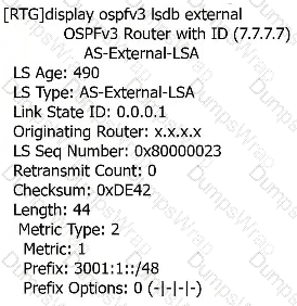
Exhibit 37.1 — Original topology/configuration figure
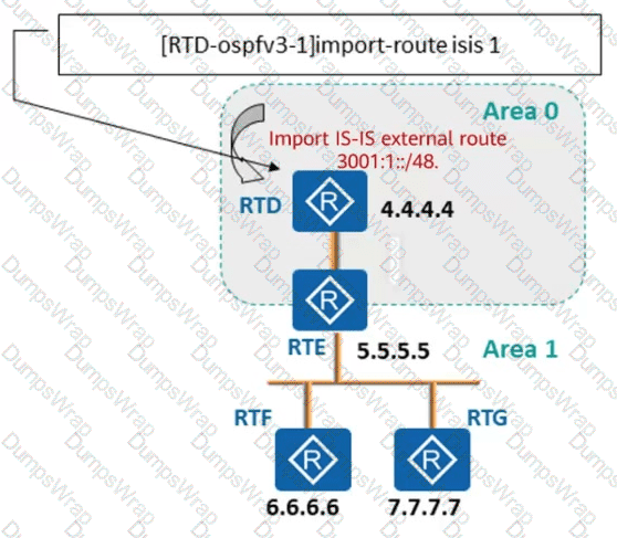
Exhibit 37.2 — Original topology/configuration figure
Options:
4.4.4.4
7.7.7.7
5.5.5.5
6.6.6.6
Answer:
AExplanation:
Huawei Reference Verification:
Huawei OSPFv3 defines an AS-External-LSA as a link-state advertisement originated by an ASBR that imports external reachability into the OSPF domain. The LSA's Advertising Router field retains the 32-bit router ID of the originating ASBR as the advertisement is flooded through different areas and received by downstream nodes. RTD imports the prefix 3001:1::/48 and has router ID 4.4.4.4; RTG merely examines the resulting LSDB. The Originating Router is therefore 4.4.4.4, not RTG's router ID or an intermediate router's identifier.
Technical Deep Dive:
A is correct. RTD acts as the OSPFv3 ASBR by executing an IS-IS route import. The external IPv6 prefix is described in an OSPFv3 AS-External-LSA, which is distributed to other areas according to OSPFv3 flooding rules. Although OSPFv3 carries IPv6 routing information, its Router ID remains a 32-bit identifier displayed in dotted-decimal form. RTD's Router ID is 4.4.4.4. RTE (5.5.5.5), RTF (6.6.6.6) and RTG (7.7.7.7) can receive and propagate the LSA but do not replace the advertising router field. The identity is crucial because routers use the ASBR and routing information in the LSDB to calculate how to reach the external destination. The command `display ospfv3 lsdb external` provides the relevant LSA fields, including the Originating Router and advertised external prefix.
───────────────────────────────────────────────────────
The new metro network is anticipated to converge fixed and mobile networks. In this type of network, every device must process services and forward data.
Options:
TRUE
FALSE
Answer:
BExplanation:
Huawei Reference Verification:
Huawei CloudMetro differentiates network-service functions from the underlying physical forwarding infrastructure. Centralized service and resource management can coexist with distributed forwarding elements. The cloud-based BNG architecture demonstrates this specifically: the vBRAS control plane coordinates subscriber sessions, authentication-related procedures, and service policies, while vBRAS user-plane devices execute high-speed packet forwarding. Thus, sharing one fixed-mobile transport infrastructure does not imply that every intermediate network element must perform subscriber service processing. The architecture assigns distinct responsibilities to control, service-edge, and transit forwarding components.
Technical Deep Dive:
The statement is FALSE. Fixed-mobile convergence requires a coordinated network, not identical service functionality in every router. Service-edge devices including MSEs and BNGs may terminate subscribers, allocate addresses, enforce policies, or maintain customer VPN state. Transit devices primarily carry traffic between access, aggregation, and backbone nodes. An MPLS P router can switch labels without hosting customer VPN routing tables. Likewise, an IPv6 transit router can forward an SRv6 packet by its IPv6 destination without executing the SID's endpoint service behavior. CUPS further separates control-plane subscriber management from data-plane forwarding. Routing CPUs calculate state and install entries, while NP/ASIC forwarding engines conduct line-rate lookups, encapsulation, policing, and queue management. Independent scaling of subscriber-control systems and packet-forwarding resources is one of the architecture's major advantages. Therefore, the assertion that every device must both process services and forward data is too broad.
───────────────────────────────────────────────────────
Which of these statements is incorrect regarding SRv6 SFC?
Options:
SRv6-aware SFs can identify and process received SRv6 packets.
SRv6-unaware SFs can implement the SFC functionality without requiring SF proxy configuration.
SRv6-unaware SFs cannot identify SRv6 packets and therefore discard them upon receipt.
The SIDs of SRv6-aware SFs can be directly orchestrated into SFC paths to implement the SFC functionality.
Answer:
BExplanation:
Huawei Reference Verification:
Huawei's SRv6 Service Function Chaining architecture distinguishes SRv6-aware functions capable of recognizing service-chain encapsulation from SRv6-unaware functions such as conventional firewalls or load balancers. An aware SF can execute or be associated with an SRv6 SID within the orchestrated chain. An unaware SF cannot independently process the required SRv6 service-chain behavior; an SRv6/SFC proxy adapts the incoming packet to the SF's expected format and restores the forwarding context afterward. Therefore B, claiming that an unaware SF can implement the chain without an appropriate proxy, is incorrect.
Technical Deep Dive:
B is incorrect. SFC directs service traffic through a defined sequence of middleboxes or virtual network functions, such as firewall, IPS and load balancer. SRv6 uses SIDs to encode the forwarding and service behaviors of this chain. SRv6-aware functions can recognize the relevant encapsulation and participate directly. An SRv6-unaware appliance may process ordinary IPv4 or IPv6 but cannot execute the specialized SRv6 service-chain instructions; a proxy handles encapsulation, decapsulation or metadata adaptation so that the appliance can operate normally. The proxy also ensures that packets returning from the service function rejoin the intended segment list. D is correct in the intended model because aware functions can be represented by orchestratable service SIDs. C is overbroad if interpreted as saying every unaware device categorically discards every IPv6 packet, but it captures the operational limitation that the device cannot process SRv6 chain metadata unassisted.
───────────────────────────────────────────────────────
Under which of the following conditions must OSPF TE and IS-IS TE flood link information?
Select all that apply.
Options:
An LSP cannot be established because resources are insufficient to reserve bandwidth.
A link is activated or deactivated.
The IGP TE flooding interval elapses.
The link attribute changes.
Answer:
A, B, C, DExplanation:
Huawei Reference Verification:
Huawei's OSPF TE and IS-IS TE implementations flood link-state and traffic-engineering information so that routers and traffic-engineering controllers can maintain an accurate TEDB. Triggers include topology changes when links become active or fail, changes in TE attributes, and periodic refresh when the flooding interval expires. In addition, insufficient bandwidth resources discovered during LSP setup can prompt updated TE resource advertisements so that other path-computing nodes have current information. These update conditions keep link attributes, bandwidth availability, and topology consistent throughout the routing domain. Thus all four conditions are relevant.
Technical Deep Dive:
A, B, C and D are correct. Traffic Engineering uses information beyond basic reachability: maximum reservable bandwidth, unreserved bandwidth, TE metrics and administrative groups/affinities may determine whether a constrained LSP can be established. Link activation or failure requires an immediate topology update. Administrative-group or bandwidth changes may affect which links remain eligible. TE refresh intervals ensure that relevant advertisements remain current, while a failed bandwidth reservation can trigger an availability update so other computations avoid the exhausted resource. OSPF TE distributes information in opaque LSAs, and IS-IS TE uses appropriate TLVs. CSPF relies on these advertisements to build the traffic-engineering database and determine paths meeting service requirements. Missing or delayed updates can cause setup failures or inappropriate path selection. The precise event thresholds and suppression timers are release- and configuration-dependent, but each listed condition can prompt TE link-state advertisement.
───────────────────────────────────────────────────────
Assume Flex-Algo is configured on a device and a tunnel policy is set for the device to preferentially select a Flex-Algo-based SR-MPLS BE tunnel. Under which of the following conditions would a VPN route recurse to the Flex-Algo-based SR-MPLS BE tunnel?
Select all that apply.
Options:
Affinity
Color attribute
Next-hop address of the route
Algorithm ID
Answer:
B, CExplanation:
Huawei Reference Verification:
Huawei uses a BGP Color Extended Community to associate service routes with transport characteristics and a BGP next-hop address to identify the transport destination. A tunnel policy can prefer SR-MPLS Best Effort tunnels calculated using Flex-Algo. The service route's color identifies the desired algorithm or constrained transport slice, and the next hop identifies the endpoint that the tunnel must reach. The Flex-Algo algorithm ID defines how the routing topology is calculated, while link affinity influences eligible links within that algorithm. Color and BGP next hop are the route-level recursion matching information; accordingly B and C are correct.
Technical Deep Dive:
B and C are correct. A Flex-Algo definition builds a separate constrained SPF topology using algorithm-specific attributes such as metrics and administrative group restrictions. Tunnel policies can map service colors to appropriate Flex-Algo paths. When a VPN route arrives, its BGP Color Extended Community describes the desired transport behavior, and its next-hop address identifies the remote PE or tunnel endpoint. The device matches that pair against eligible tunnels and installs the resulting forwarding recursion. Affinity (A) can control which physical links participate in the algorithm-specific topology, but is not the route's direct matching attribute. Algorithm ID (D) identifies the computation algorithm rather than independently defining the BGP route recursion key. After resolution, forwarding NP/ASIC hardware applies the programmed SR-MPLS labels and next-hop group. This separation allows a carrier to provide differentiated transport characteristics without manually defining an explicit LSP for every VPN route.
───────────────────────────────────────────────────────
Which of the following SIDs encapsulates the outer destination address for BIERv6 multicast packets?
Options:
End.BIERv6 SID
End.DT6 SID
End.DX6 SID
End.BIER SID
Answer:
DExplanation:
Huawei Reference Verification:
Huawei BIERv6 encapsulates a Bit Index Explicit Replication forwarding header in IPv6 and defines an End.BIER SID for Bit-Forwarding Router processing. The outer IPv6 destination address contains the End.BIER SID of the next BIERv6 forwarding router. On receipt, the local node processes the BIERv6 header and BitString, consults its BIFT, and determines the required downstream replicas. An End.DT6 service SID or End.DX6 cross-connect SID implements a different SRv6 endpoint behavior. End.BIER is therefore the correct choice.
Technical Deep Dive:
D is correct. BIERv6 enables efficient multicast transport without maintaining conventional per-flow (S,G) state on every transit node. The packet carries a BitString identifying destination BFRs and an outer IPv6 address identifying the next-hop BIER-aware forwarding behavior. Each BFR receives the packet addressed to its End.BIER SID, reads the BitString, looks up forwarding choices in the Bit Index Forwarding Table, and creates the packet copies necessary for different downstream branches. The next hop's End.BIER SID is installed in the outgoing outer IPv6 destination. End.DT6 is associated with decapsulation into an IPv6 routing table; End.DX6 sends a decapsulated packet toward a specific IPv6 adjacency. Neither provides the BIERv6 replication function. On capable carrier hardware, BitString processing and replica creation can be performed in forwarding silicon.
───────────────────────────────────────────────────────
Which of the following key factors must be considered when designing an IGW for an IP core network?
Select all that apply.
Options:
Routing policy scale
Hardware capacity of devices
Route transport capability
Security
Answer:
A, B, C, DExplanation:
Huawei Reference Verification:
Huawei's carrier IP gateway design requires sufficient policy-processing scale, forwarding resources, routing-information transport capacity, and security controls. An Internet Gateway can receive large external BGP route sets, process prefix and community policies, and advertise selected reachable destinations into other parts of the backbone. Its interface bandwidth, routing-table resources, CPU and memory, and forwarding ASIC capacity must match expected demand. As a boundary between autonomous networks, it also requires routing filtering and defenses against harmful or unauthorized traffic. These are complementary responsibilities: a high packet throughput specification does not compensate for poor BGP scalability or insufficient security. All four proposed factors must be considered.
Technical Deep Dive:
A, B, C, and D are correct. Routing-policy scale covers BGP prefixes, filters, route preference, community and AS-path attributes, and traffic-engineering decisions. Hardware capacity includes interface rates, route and ACL table sizes, packet processing, control CPU, memory, and line-card traffic-management capability. Route transport capability covers BGP session scale, route propagation, policy operations, and convergence under network changes. Security requires route filtering, ingress antispoofing, management-plane access control, control-plane policing, and appropriate DDoS mitigation. On Huawei NetEngine platforms, NP/ASIC forwarding hardware performs FIB lookups, ACL matching, classification, and QoS handling, whereas the control-plane subsystem maintains BGP route state. Designers must size these subsystems independently. `display bgp peer`, `display bgp routing-table`, `display cpu-usage`, `display memory-usage`, and routing statistics can provide operational evidence. A good IGW design satisfies all four domains simultaneously rather than optimizing only raw bandwidth.
───────────────────────────────────────────────────────
Which of the following statements is incorrect regarding SRv6 protection technologies?
Options:
In an SRv6 TE Policy scenario, if a specified explicit node fails, TI-LFA cannot be used to restore services.
TI-LFA can be used in both SRv6 BE and SRv6 TE Policy scenarios.
In an SRv6 TE Policy scenario, after headend-based fault detection is configured, the device sets the segment list to down and deletes the segment list entry as long as more than two SRv6 SIDs in the segment list do not exist in the topology.
In an L3VPN scenario, if traffic is carried over an SRv6 TE Policy, both egress protection and VPN FRR can protect PEs.
Answer:
CExplanation:
Huawei Reference Verification:
Huawei SRv6 TE Policies contain candidate paths and segment lists whose validity depends on reachability of their mandatory SIDs. Headend fault detection can mark a segment list Down when an essential SID becomes unreachable or disappears from the relevant topology. There is no general rule that more than two SIDs must fail before a segment list is invalidated. Protection may use another valid segment list, candidate path, or VPN-level alternate route. The threshold claim in C is therefore incorrect. The other options describe intended TI-LFA and service-PE protection functions with the deployment constraints applicable to explicit SRv6 paths.
Technical Deep Dive:
C is incorrect because a mandatory SID disappearing from the topology can invalidate a segment list regardless of whether other SIDs remain reachable. SRv6 TE Policy selects candidate paths containing ordered segment lists; the headend must ensure the required path instructions remain viable. It may switch to another candidate or segment list when one becomes invalid. TI-LFA supplies precomputed local protection for eligible link or node failures but cannot always bypass a failed explicitly required segment while still honoring the specified TE path. SRv6 BE and SRv6 TE Policy may both use local protection subject to endpoint and path constraints. In an L3VPN, VPN FRR or egress protection can also protect service reachability against PE failure. The key distinction is local repair versus headend path validity. The specific deletion and invalidation behavior should follow the product release's headend fault-detection implementation rather than an arbitrary count of missing SIDs.
───────────────────────────────────────────────────────
Which of these statements are correct regarding IS-IS reliability parameters on a 5G transport network?
Select all that apply.
Options:
It is recommended that you set the maximum delay, initial delay, and each incremental delay to 1s, 50 ms, and 50 ms respectively for the SPF calculation timer.
It is recommended that you enable TI-LFA and deploy microloop avoidance.
It is recommended that GR be enabled so that the neighbor status and database remain unchanged after the neighbor relationship is disconnected.
It is recommended that you set the maximum delay, initial delay, and each incremental delay to 1s, 50 ms, and 50 ms respectively for the LSP generation timer.
Answer:
A, B, C, DExplanation:
Huawei Reference Verification:
Huawei's 5G transport IS-IS reliability design combines intelligent SPF and LSP-generation timers with precomputed TI-LFA protection, microloop avoidance and Graceful Restart. Maximum, initial and incremental delays of 1 second, 50 milliseconds, and 50 milliseconds are a recommended convergent tuning pattern for both SPF and LSP generation in the intended solution. TI-LFA protects eligible failures locally, and microloop avoidance reduces transient forwarding loops when routers converge at different times. Graceful Restart can preserve continuity during supported routing-control restarts. These complementary functions support all four options, provided GR is not misinterpreted as protecting against arbitrary permanent neighbor disconnection.
Technical Deep Dive:
A, B, C and D represent the intended reliability design. The intelligent SPF timer reacts rapidly to a first topology change, then increases the wait during repeated changes to control CPU load. The LSP-generation timer similarly limits excessive update flooding while maintaining rapid distribution of meaningful state changes. The representative values are 1000, 50, 50 in milliseconds. TI-LFA precomputes backup next-hop instructions and allows rapid repair when a link or protected node fails; microloop avoidance reduces short-lived loops during distributed reconvergence. IS-IS GR permits routing-state and forwarding continuity across an eligible process restart with neighbor helper behavior, but not across every physical failure. Example VRP commands are `isis 1`, `timer spf 1000 50 50`, `timer lsp-generation 1000 50 50`. Exact timer syntax and protection availability must match the device release. A proper reliability plan combines fault detection, local switching, and stable eventual convergence.
───────────────────────────────────────────────────────
The topology shown is a typical transport-network access-layer structure. Each core-network device is dual-homed to two CEs, and the CEs and PEs are interconnected in a square-loop topology. The access layer must carry voice and signaling services. Two VPN instances must be configured on each CE to isolate voice services from signaling services and provide security and QoS. Signaling services are transmitted in active/standby mode, while voice services are transmitted in load-balancing mode. VRRP must be enabled between the two CEs to terminate signaling flows. From the perspectives of network robustness and architectural suitability, which statements about this topology are correct?
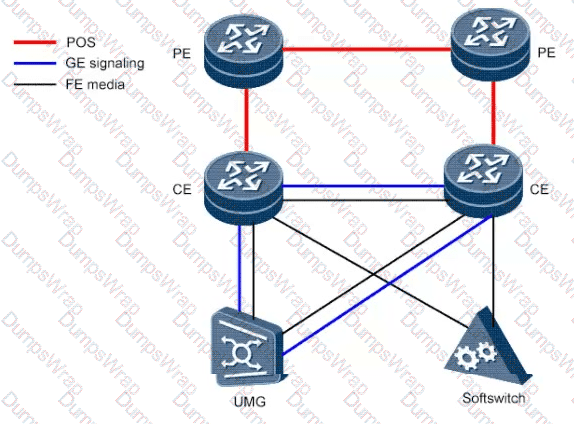
Exhibit 60.1 — Original topology/configuration figure
Select all that apply.
Options:
GE links, not POS links, should be used between CEs and PEs.
GE and FE links between two CEs need be added to an Eth-Trunk to improve reliability.
The total bandwidth of the link between two CEs should be greater than or equal to the bandwidth of the CE-PE interconnection link.
The voice services should be carried on GE links, and the signaling services should be carried on FE links.
Answer:
C, DExplanation:
Huawei Reference Verification:
Huawei's square-loop carrier access design uses dual-homed CEs and redundant PEs to maintain voice and signaling service reachability during individual failures. Separate VPN instances protect service isolation and enable differentiated QoS. A CE-to-CE link must have sufficient engineered bandwidth to carry the traffic diverted to it during failure conditions; a conservative recommendation is capacity at least as large as the relevant CE–PE interconnection. Higher-volume media services can be mapped to GE and lower-volume signaling services to FE in the intended equipment layout. GE and FE ports cannot simply be mixed in one conventional Eth-Trunk, and choosing GE rather than POS for every CE–PE connection is not an unconditional rule. Thus C and D are the intended topology choices.
Technical Deep Dive:
C and D are the intended answers. The topology has two CEs connected to redundant PEs, with a square-loop design and separate voice/media and signaling VPN instances. VRRP provides active/standby gateway behavior for the signaling service, while voice media can use load-balanced forwarding according to service design. During a CE–PE failure the surviving CE-to-CE connection may carry diverted traffic; the inter-CE link should be sized to the expected failure-state traffic, and engineering it to at least the CE–PE bandwidth is a conservative design objective. GE has higher capacity and is suitable for voice/media concentration, while FE may suffice for the smaller signaling load. Option A incorrectly presents GE-only CE–PE transport as mandatory; POS may also carry routed transport services when appropriate. Option B incorrectly proposes mixing GE and FE links as Eth-Trunk members despite compatibility and rate requirements. QoS priorities and bandwidth reservations must also preserve low latency and low jitter for real-time services. Neither C nor D is a universal physical law: capacity and interface rates should match measured worst-case failure traffic and service requirements.
During path computation, when multiple paths have the same metric, CSPF chooses one using tie-breaking policies. Which of the following is not an available tie-breaking policy?
Options:
Select the link with the highest proportion of the used bandwidth to the maximum reservable bandwidth.
Select the link with the smallest proportion of the used bandwidth to the maximum reservable bandwidth.
Select the link with the smallest proportion of a single link cost to the total link cost.
Select a link randomly.
Answer:
CExplanation:
Huawei Reference Verification:
Huawei MPLS TE documentation describes three CSPF tie-breaking selections for candidate paths having equal applicable metrics: most-fill, least-fill, and random. The fill-based strategies compare utilized versus reservable link bandwidth, while random selection chooses among equivalent candidate paths without using the utilization ratio. A ratio comparing the cost of an individual link with the cumulative cost of the entire path is not a defined CSPF tie-breaking policy. Therefore C is the unsupported choice.
Technical Deep Dive:
C is correct. CSPF first prunes paths that violate configured TE constraints, such as bandwidth reservation and affinity, and then computes shortest eligible paths. When multiple paths have equal cost, the tie-breaking policy selects among them. Huawei's supported modes include `most-fill`, `least-fill`, and `random`. The most-fill and least-fill mechanisms use relevant bandwidth utilization proportions; random allows non-deterministic selection among equal candidates. Option C introduces a ratio of individual-link cost to total path cost, which is not a tie-breaking option. Link metrics have already informed the primary shortest-path calculation. A representative configuration is `mpls`, followed by `mpls te tie-breaking least-fill` in the applicable view; syntax and semantics should be checked for the software version. Understanding the boundary between constraint filtering, SPF metric computation, and equal-cost tie-breaking prevents confusion in path-engineering questions.
───────────────────────────────────────────────────────
In an intelligent cloud-network scenario, NCE centrally computes and delivers SRv6 Policies. Which statements about the BGP-LS IPv6 design are correct?
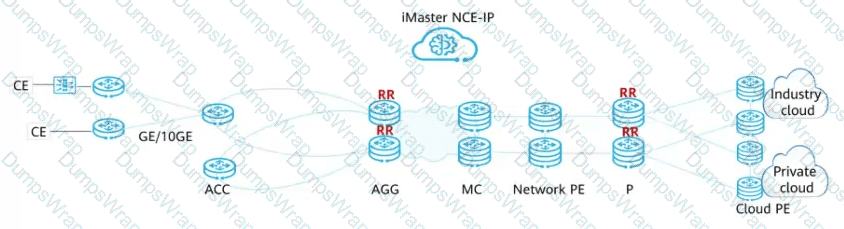
Exhibit 15.1 — Original topology/configuration figure
Select all that apply.
Options:
The ACC and AGG establish a BGP-LS peer relationship. The ACC uses IGP to flood information such as the topology, bandwidth, and link delay to the AGG.
The AGG establishes a BGP-LS peer relationship with the P on the cloud backbone network, and advertises information such as the collected topology, bandwidth, and link delay to the P through BGP-LS.
The MC, cloud PE, and network PE use IGP to flood information about the aggregation and core layers, such as the topology, bandwidth, and link delay, to the P. The P establishes a BGP-LS IPv6 peer relationship with iMaster NCE-IP, and uses BGP-LS to report the information to iMaster NCE-IP.
BGP-LS IPv6 is deployed between the headend of an SRv6 Policy and the RR and between the headend and the controller to deliver SRv6 Policy information.
Answer:
A, B, CExplanation:
Exact Extract — Huawei Training Material (Automatic SDN Network O & M, p.26):
“BGP-LS: BGP Link-state Protocol, BGP extension, which is used to summarize topology information collected by IGP and send the information to the upper-layer controller. This feature is mainly used when the controller computes paths in a centralized manner.”
Huawei Reference Verification:
Huawei's Automatic SDN O & M curriculum defines BGP-LS as a BGP extension that summarizes topology information collected by IGP and sends it to a controller for centralized path computation. The intelligent cloud bearer design collects access, aggregation, and core topology, including bandwidth and delay. It uses BGP-LS peering/reporting relationships from ACC through AGG and backbone reporting nodes toward iMaster NCE-IP. In contrast, policies computed by the controller are signaled through the BGP IPv6 SR Policy address family rather than BGP-LS. This distinction establishes A, B, C and excludes D in the depicted hierarchical reporting model.
Technical Deep Dive:
A, B and C are correct for the illustrated architecture. The access and aggregation layers provide IGP-distributed topology and traffic engineering data, including link state, metrics and delay. BGP-LS speakers transport relevant node, link and prefix information toward the backbone reporting devices and NCE. The controller uses this combined topology to compute SRv6 Policy segment lists meeting SLA constraints. Option D confuses topology reporting with policy distribution: BGP-LS exports network state; BGP IPv6 SR Policy conveys policy information to the headend for traffic steering. A BGP-LS route may encode link, node or prefix attributes but does not replace the SR Policy NLRI. Separating these address families allows a controller to obtain topology information independently of its chosen path-delivery mechanism. PCEP is another technology that can assist computation and LSP management in supported deployments.
───────────────────────────────────────────────────────
Which of the following statements is incorrect about address planning for an IP core network?
Options:
A certain amount of address space needs to be reserved for service growth.
Planned addresses should be consecutive whenever possible.
It is recommended that private network addresses be used as device interconnection addresses to save addresses.
Address aggregation should be used to reduce intra-domain routes whenever possible, speeding up network convergence and facilitating fault locating.
Answer:
CExplanation:
Huawei Reference Verification:
Huawei's backbone routing design emphasizes aggregate reachability, consistent address blocks, and controlled routing-table size. Route aggregation advertises a summary prefix instead of numerous more-specific prefixes and benefits from hierarchical, consecutive address allocation. Capacity reservations at each network layer prevent disruptive renumbering as access and backbone infrastructure grows. Choosing private IPv4 addresses for interconnections solely to conserve address space can create overlaps and complications when carrier domains are interconnected. This supports C as the intended incorrect recommendation, while recognizing that private addressing can still be legitimate in a properly isolated routing domain.
Technical Deep Dive:
C is the intended incorrect statement. Carrier backbone addressing must enable unique infrastructure identification, predictable expansion, route summarization, and efficient troubleshooting. Reserving address blocks for planned growth supports new links, loopbacks and router additions (A). Consecutive assignments within regional and hierarchical address blocks support maintenance and aggregate advertisements (B). Aggregation reduces protocol processing and the number of forwarding entries when summarization boundaries are properly positioned (D). Private RFC 1918 addresses are not categorically forbidden on internal point-to-point links; they can be appropriate when the operator controls the entire routing domain. However, overlaps and external interconnection requirements complicate indiscriminate use, so conserving public addresses alone is not a sufficient planning rule. Engineers should validate address allocations with `display ip interface brief`, `display ip routing-table`, and `display ip routing-table statistics`. On forwarding hardware, aggregation can reduce FIB consumption but must not hide needed individual reachability.
───────────────────────────────────────────────────────
In the transport network shown, two-level RRs are deployed, and RTA has the directly connected network segment 10.1.1.0/30. Which of the following statements about the BGP deployment solution are incorrect?
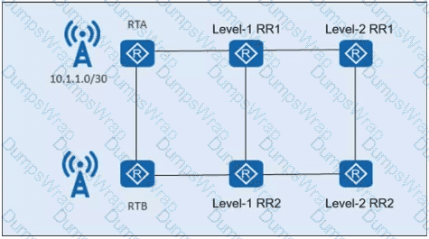
Exhibit 28.1 — Original topology/configuration figure
Options:
To enable level-2 RRs to learn the route to network segment 10.1.1.0/30, the level-2 RRs must be configured as clients of level-1 RRs.
It is recommended that RRs of the same level be configured with the same cluster ID.
RRs of the same level must be configured as clients of each other.
RTA and RTB can establish IBGP peer relationships with two level-1 RRs. RTA and RTB do not need to establish an IBGP peer relationship.
Answer:
CExplanation:
Huawei Reference Verification:
Huawei's hierarchical BGP route-reflector deployment lets a lower-level RR be a client of an RR at a higher level, extending route distribution without requiring client-to-client full-mesh sessions. Redundant RRs serving the same cluster can use the same cluster ID. Ordinary edge clients can peer with their selected Level-1 RRs and learn reflected routes without peering with one another. RRs on the same tier do not have to be configured as each other's route-reflector clients; non-client IBGP relationships or other hierarchy rules can supply the required connectivity. Therefore the assertion that same-level RRs must be each other's clients is incorrect.
Technical Deep Dive:
C is incorrect. In the illustrated two-level design, RTA and RTB each peer with the redundant Level-1 RRs; Level-2 RRs operate as clients of the Level-1 layer to receive the needed routes. A direct IBGP adjacency between RTA and RTB is not mandatory because both can learn eligible routes through their RRs. RRs in a shared redundancy cluster may use the same cluster identifier for consistent loop detection, but this is not a universal rule across unrelated clusters. Route-reflection client relationships are directional configuration properties: not all RRs at one level need to treat their peer RRs as clients. RRs may establish ordinary non-client peering where appropriate. The BGP Originator ID and Cluster List attributes prevent reflection loops as routes pass through the hierarchy. Route deployment must also consider route visibility and path diversity; making every same-tier RR a mutual client is neither necessary nor a normal scaling principle.
───────────────────────────────────────────────────────
