Data Center Associate (JNCIA-DC) Questions and Answers
In a five-stage IP fabric, what is the role of the superspine layer?
Options:
It ensures that every leaf device has a physical connection to every spine device in the five-stage IP fabric.
It establishes a common BGP autonomous system that combines multiple three-stage IP fabric spine-and-leaf nodes into one autonomous system.
It creates a Layer 2 underlay network between the spine nodes and leaf nodes in the five-stage IP fabric.
It interconnects the spine layers in different three-stage IP fabric pods in a data center at the same site or across different sites.
Answer:
DExplanation:
A five-stage IP fabric is typically used when a single pod, even with a three-stage design, cannot meet overall scale requirements for port count, bandwidth, or modular growth. In this model, the data center is built from multiple fabric pods, where each pod is commonly a three-stage topology that includes leaf switches and one or more spine layers. The superspine layer provides the interconnect that ties these pods together into a larger fabric. Functionally, superspines create high-capacity, routed connectivity between the spine layers of different pods so that endpoints in any pod can reach endpoints in any other pod using consistent Layer 3 forwarding principles and equal-cost multipath behavior where applicable.
Option D is correct because the superspine layer is the aggregation and inter-pod transit layer. It does not exist to force every leaf to connect to every spine across the entire multi-pod deployment. That full mesh property is preserved within a pod, not across the entire site at extreme scale. The superspine layer also does not create a Layer 2 underlay; modern fabrics use a routed underlay to avoid spanning tree limitations and to enable deterministic multipathing. Finally, the superspine layer is not defined by creating a single common BGP autonomous system; autonomous system design is a policy choice, while the superspine role is a physical and logical interconnection function between pods.
What is a function of an integrated routing and bridging IRB interface?
Options:
to route traffic between different VLANs
to encrypt traffic between network segments
to bridge traffic within the same VLAN
to provide Network Address Translation NAT
Answer:
AExplanation:
In Junos-based data center switching, an IRB interface is the Layer 3 gateway that is logically associated with a Layer 2 VLAN or bridge domain. The VLAN provides Layer 2 bridging inside the broadcast domain, while the IRB interface provides the routed interface that enables hosts in that VLAN to reach destinations outside their local subnet. This is the standard mechanism used for inter-VLAN routing on Juniper switches and for providing default gateway services to servers connected to access ports or VLAN-tagged trunks.
Operationally, endpoints in a VLAN use the IRB interface IP address as their default gateway. Frames destined to a remote subnet are bridged at Layer 2 to the IRB gateway MAC address, and then the packet is routed at Layer 3 based on the routing table. This allows a single device to perform both bridging within the VLAN and routing between VLANs or to other routed interfaces, which is why the concept is called integrated routing and bridging.
IRB does not encrypt traffic and does not provide NAT by itself; those functions are typically associated with security services features and firewall platforms. IRB is also not the mechanism that performs pure bridging within the same VLAN, because bridging is handled by the VLAN or bridge domain and the Ethernet switching table.
Which two statements are correct about aggregate routes and generated routes? (Choose two.)
Options:
An aggregate route does not have a forwarding next hop.
An aggregate route has a forwarding next hop.
A generated route has a forwarding next hop.
A generated route does not have a forwarding next hop.
Answer:
A, CExplanation:
Aggregate routes and generated routes are used to create summarized routes in Junos, but they behave differently in terms of forwarding.
Step-by-Step Breakdown:
Aggregate Routes:
An aggregate route summarizes a set of more specific routes, but it does not have a direct forwarding next hop. Instead, it points to the more specific routes for actual packet forwarding.
Generated Routes:
A generated route also summarizes specific routes, but it has a forwarding next hop that is determined based on the availability of contributing routes. The generated route can be used to directly forward traffic.
Juniper Reference:
Aggregate and Generated Routes: In Junos, aggregate routes rely on more specific routes for forwarding, while generated routes can forward traffic directly based on their next-hop information.
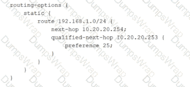
Referring to the exhibit, which statement is correct about the 192.168.1.0/24 route?
Options:
The 192.168.1.0/24 route is load balanced across both next hops.
The 192.168.1.0/24 route will select 10.20.20.254 as the next hop.
The 192.168.1.0/24 route will select 10.20.20.253 as the next hop.
The 192.168.1.0/24 route is not installed in the routing table.
Answer:
BExplanation:
The configuration defines a static route for 192.168.1.0/24 with a primary next hop of 10.20.20.254 and a qualified-next-hop of 10.20.20.253 with preference 25. In Junos, qualified next hop is used to create preference-ranked redundancy for a static route, typically primary and backup forwarding. The key behavior is that the best, lowest preference path is selected as active. For static routes, the default preference for the route and its primary next hop is lower than 25 unless you explicitly raise it. Because the qualified-next-hop is configured with preference 25, it is less preferred than the primary next hop, so 10.20.20.254 remains the selected next hop during normal operation.
This is not load balancing. Junos does not automatically install both next hops for forwarding simply because more than one next hop is configured when one is qualified with a higher preference. Instead, the qualified next hop is held in reserve and is used only when the primary next hop becomes unusable, such as when it is no longer resolvable or the associated forwarding condition fails. Therefore, the route is expected to be installed and active using 10.20.20.254 under normal conditions, with 10.20.20.253 acting as a backup path.
You are troubleshooting an issue and notice that an interface is down.
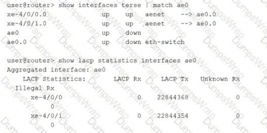
Referring to the exhibit, what is the cause of the problem?
Options:
The remote device is not using any routing protocols that require LACP.
The local device does not have LACP configured.
The local device is not using any routing protocols that require LACP.
The remote device does not have LACP configured.
Answer:
DExplanation:
The exhibit shows the physical member interfaces xe-4/0/0 and xe-4/0/1 are up, but the aggregated Ethernet interface ae0 is down. This commonly indicates that the bundle is not successfully forming at the link aggregation control plane level, even though the physical links are operational. The key evidence is in the LACP statistics. The local device is transmitting LACP packets at a very high count on both member links, but the LACP receive counters remain at zero. That means the local system is actively sending LACP Data Units but is not receiving any LACP Data Units back from the far end.
When an LACP-based bundle is configured, the two sides must exchange LACP control packets to negotiate membership and move the links into collecting and distributing state. If the remote side is not configured for LACP, or is configured for a static aggregate without LACP, it will not send LACP packets. In that situation, the Junos device continues transmitting LACP but never receives a response, and the aggregate does not come up, leaving the logical ae interface down even though the member links are physically up.
Therefore, the cause is that the remote device does not have LACP configured. The routing protocol choices on either side are irrelevant to LACP negotiation, and the local device clearly has LACP enabled because it is transmitting LACP packets.
Exhibit:
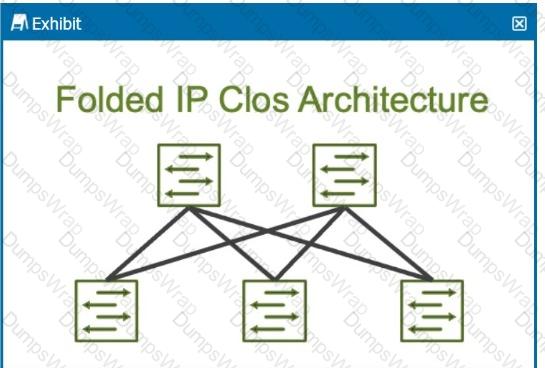
How many stages are shown in the exhibit?
Options:
2
5
6
3
Answer:
DExplanation:
The exhibit shows a Folded IP Clos Architecture, which is also referred to as a 3-stage Clos network design. This architecture typically consists of two layers of switches:
Spine Layer: The top row of switches.
Leaf Layer: The bottom row of switches.
Step-by-Step Breakdown:
Clos Architecture:A 3-stage Clos network has two types of devices: spine and leaf. In this design, each leaf switch connects to every spine switch, providing a high level of redundancy and load balancing.
Stage Explanation:
Stage 1: The first set of leaf switches.
Stage 2: The spine switches.
Stage 3: The second set of leaf switches.
The Folded Clos architecture shown here effectively "folds" the 3-stage design by combining the ingress and egress leaf layers into one, reducing it to two visible layers, but still maintaining the overall 3-stage architecture.
Juniper Reference:
IP Clos Architecture: The 3-stage Clos design is commonly used in modern data centers for high availability, redundancy, and scalability.
What are two BGP message types? Choose two.
Options:
open
hello
update
LSA
Answer:
A, CExplanation:
BGP uses a small set of well-defined message types to form and maintain peerings and to exchange routing information. The Open message is used during session establishment after the TCP connection is up. It communicates the parameters required to form the BGP session, such as the BGP version, the autonomous system number, the negotiated hold time, the BGP identifier, and optional capabilities. Capabilities are especially important in data center designs because they enable features such as 4 byte ASNs, route refresh, and EVPN signaling when applicable.
The Update message is the core mechanism BGP uses to advertise reachability and to withdraw routes that are no longer valid. In a data center underlay using EBGP, Update messages carry the prefixes that represent loopbacks and point-to-point links, enabling leaf and spine reachability. In an EVPN control plane, Update messages carry EVPN Network Layer Reachability Information to distribute MAC and IP reachability and multihoming information across the fabric.
Hello is not a BGP message type. Hello is commonly associated with protocols like OSPF, IS-IS, and some discovery mechanisms. LSA is not a BGP message type either; Link State Advertisements are specific to OSPF.
Which state in the adjacency process do OSPF routers check the MTU size?
Options:
Init
Exchange
Done
ExStart
Answer:
BExplanation:
In OSPF, routers exchange link-state information in different stages to establish full adjacency. The MTU size is checked during the Exchange state.
Step-by-Step Breakdown:
1. OSPF Adjacency Process:
o OSPF routers go through multiple stages when forming an adjacency: Down, Init, 2-Way, ExStart, Exchange, Loading, and Full.
2. Exchange State:
o During the Exchange state, OSPF routers exchange Database Description (DBD) packets to describe their link-state databases. The MTU size is checked at this stage to ensure both routers can successfully exchange these packets without fragmentation.
o If there is an MTU mismatch, the routers may fail to proceed past the Exchange state.
Juniper Reference:
· MTU Checking in OSPF: Junos uses the Exchange state to check for MTU mismatches, ensuring that routers can properly exchange database information without packet fragmentation issues.
When using spine and leaf fabric architectures, what is the role of each device? (Choose two.)
Options:
Spine nodes are used for host connectivity.
Spine nodes are used for transit to other leaf nodes.
Leaf nodes are used for traffic to other leafs.
Leaf nodes are used for host connectivity.
Answer:
B, DExplanation:
In a spine-leaf fabric architecture, which is commonly used in data center designs, each device has a distinct role to ensure efficient and scalable network traffic flow.
Step-by-Step Breakdown:
Spine Nodes:
The spine nodes form the backbone of the fabric and are responsible for transit traffic between leaf nodes. They connect to every leaf switch and provide multiple paths for traffic between leaf nodes, ensuring redundancy and load balancing.
Leaf Nodes:
The leaf nodes are used for host connectivity. These switches connect to servers, storage, or edge routers. They also connect to the spine switches to reach other leaf switches.
Juniper Reference:
Spine-Leaf Architecture: In Juniper's IP fabric designs, spine switches handle inter-leaf communication, while leaf switches manage host and endpoint connectivity.
Which feature should be used with a static route that has a secondary next hop with a unique route preference value? Choose one.
Options:
retain
resolve
qualified next hop
install
Answer:
CExplanation:
In Junos, a static route can be configured with multiple next hops. When you want a “primary and backup” behavior, the correct mechanism is a qualified next hop. A qualified next hop allows you to assign a different preference to each next hop for the same destination prefix. The static route with the best preference is selected as active, while the higher-preference value next hop remains available as a standby option. If the primary next hop becomes unusable, Junos can install the backup qualified next hop so forwarding continues with minimal operational change, which is a common requirement for data center edge or services routing where predictable failover is needed.
The key point in the question is “secondary next hop with a unique route preference value.” That wording maps directly to qualified next-hop behavior, because qualification is how Junos differentiates multiple next hops under the same route using distinct preference values. The retain option relates to keeping routes in the routing table under certain conditions and does not specifically create primary/backup next-hop selection based on preference. The resolve option concerns how the system resolves a next hop through another route and is not the feature that creates a preference-ranked secondary next hop. The install option is not the mechanism used to define backup next-hop preference for a static route.
Which two statements about VLANs are true? Choose two.
Options:
By default, ports in a VLAN operate in trunk mode.
A single VLAN is limited to only half of a switch's physical ports.
A single VLAN can include all of a switch's physical ports.
By default, ports in a VLAN operate in access mode.
Answer:
C, DExplanation:
In Junos Ethernet switching, a VLAN is a Layer 2 broadcast domain and can include any set of switch ports that you assign to it. There is no generic rule that limits a VLAN to only half of a switch’s physical ports. Practically, a single VLAN can include all physical ports on the switch if that is how the environment is designed, for example in a flat Layer 2 segment for a specific purpose or during a migration. This makes statement C correct.
For interface mode behavior, access mode is the default expectation for endpoint-facing Layer 2 ports where traffic is normally untagged. In Junos, when an interface is configured for Ethernet switching and no explicit trunk configuration is applied, the operational intent aligns with access behavior: the port is associated with a single VLAN and forwards frames as untagged on the wire. Trunk mode must be explicitly configured when the link needs to carry multiple VLANs using 802.1Q tagging, such as switch-to-switch uplinks or server connections that tag multiple VLANs. Therefore, statement D is correct and statement A is incorrect because trunk mode is not the default behavior.
This distinction is important in data center operations because misidentifying an access port as a trunk can lead to dropped traffic, VLAN mismatch, or unexpected flooding behavior.
Verification sources from Juniper documentation
You are creating an IP fabric underlay and want to use OSPF as your routing protocol.
In this scenario, which statement is correct?
Options:
All leaf devices must be configured in separate OSPF areas.
All leaf and spine devices must be the same model to ensure the proper load-balancing behavior.
Interface speeds should be the same throughout the fabric to ensure that all links are utilized.
All spine devices must use the same router ID.
Answer:
CExplanation:
When creating an IP fabric underlay using OSPF as the routing protocol, consistent interface speeds are important to ensure optimal traffic distribution and utilization of all links.
Step-by-Step Breakdown:
OSPF and Interface Speeds:OSPF calculates the cost of a link based on its bandwidth. The default cost calculation in OSPF is:

If interface speeds vary significantly, OSPF may choose paths with lower cost (higher bandwidth), resulting in some links being underutilized.
Equal Utilization:To ensure that all links are equally utilized in an IP fabric, it is recommended to maintain uniform interface speeds across the fabric. This ensures balanced load sharing across all available paths.
Juniper Reference:
IP Fabric with OSPF: Juniper recommends consistent interface speeds to maintain even traffic distribution and optimal link utilization in IP fabric underlay designs.
Within OSPF, what is the purpose of a designated router DR and backup designated router BDR on a broadcast network? Choose one.
Options:
to reduce the resource overhead of maintaining a full mesh of adjacencies
to ensure that only external LSAs from other routers are directed to the correct destination
to coordinate routing updates to all the other routers of the point-to-point network
to provide a backup path in case the Designated Router goes down
Answer:
AExplanation:
On broadcast network types in OSPF, such as Ethernet segments, forming a full mesh of adjacencies between every pair of routers would create significant control-plane overhead. Every router would need to maintain neighbor state with every other router, exchange database information redundantly, and flood link-state updates across many parallel adjacencies. This becomes inefficient as the number of routers on the segment grows.
To address this, OSPF elects a Designated Router and a Backup Designated Router. The DR acts as the central point for adjacency formation on that broadcast segment. Instead of each router forming full adjacencies with all others, routers form full adjacencies primarily with the DR and BDR. The DR is responsible for generating and flooding network LSAs that represent the broadcast segment and for coordinating reliable LSA flooding on that segment. This significantly reduces the number of adjacencies and the volume of duplicated database exchange and LSA flooding, which is why option A is correct.
The BDR is a standby control-plane role. It monitors the segment and is prepared to take over the DR function if the DR fails, improving stability and convergence. However, the primary purpose of having DR and BDR is the scaling benefit of reduced adjacency and flooding overhead on broadcast networks.
Which protocol is supported in an IP fabric underlay network? Choose one.
Options:
RSTP
EVPN
VXLAN
EBGP
Answer:
DExplanation:
An IP fabric underlay is the routed foundation of a modern leaf-spine data center. Its purpose is to provide scalable, deterministic Layer 3 reachability between all fabric nodes, typically using point-to-point routed links between leaves and spines. In this design, EBGP is commonly used as an underlay routing protocol because it scales well, supports clear policy boundaries, and enables fast convergence and operational simplicity. Each leaf forms EBGP sessions to each spine, advertising loopback addresses and link subnets so that overlay endpoints and control plane services can reach one another reliably.
RSTP is a Layer 2 spanning tree mechanism and is not the standard protocol for a routed underlay. EVPN is an overlay control plane used to distribute tenant reachability and multihoming information; it is not the underlay routing protocol itself. VXLAN is a data plane encapsulation used by the overlay to transport Layer 2 segments across a Layer 3 fabric; it also is not the underlay routing protocol.
In Juniper data center architectures, the underlay is intentionally kept simple and purely routed, while overlays such as EVPN VXLAN deliver multi-tenant Layer 2 and Layer 3 services on top of that underlay. EBGP fits the underlay requirement among the provided options.
Which two statements are correct about configuring VLANs? Choose two.
Options:
You must assign an IRB interface to each VLAN.
You must assign a VLAN name or ID and a Layer 2 interface to the VLAN.
You can assign one or more VLANs to a trunk mode interface.
You can assign one or more VLANs to an access mode interface.
Answer:
B, CExplanation:
On Junos switching platforms commonly used in data centers, a VLAN is a Layer 2 construct that defines a broadcast domain. To make a VLAN usable, you define the VLAN using a name and typically a VLAN ID, then associate Layer 2 interfaces with it so traffic entering those interfaces is placed into that VLAN. Without membership on interfaces, the VLAN exists in configuration but does not carry user traffic, because no ports participate in that broadcast domain.
Trunk mode interfaces are specifically designed to carry traffic for multiple VLANs over a single physical link, such as between switches, to servers using tagging, or to other network devices that understand VLAN tags. In Junos, trunking is implemented by allowing a list of VLAN IDs on the trunk so the interface accepts and forwards frames for those VLANs. This makes statement C correct.
An IRB interface is not mandatory for every VLAN. IRB is used when you want Layer 3 routing for a VLAN, typically to provide a default gateway and enable inter VLAN routing. Pure Layer 2 VLANs do not require IRB, which makes statement A incorrect.
Access mode interfaces are intended to connect to a single endpoint and carry traffic for a single VLAN, so assigning multiple VLANs to an access interface is not correct in standard access mode behavior, making statement D incorrect.
What are three examples of martian addresses? Choose three.
Options:
224.0.0.0/4
172.36.0.0/24
192.0.0.0/24
198.60.0.0/16
127.0.0.0/8
Answer:
A, C, EExplanation:
In Junos routing and security contexts, martian addresses are IP prefixes that should not appear as valid, routable sources or destinations on normal interfaces because they are reserved, special-purpose, or otherwise not usable for general unicast forwarding. Treating these as invalid helps protect the control plane and prevents leakage of nonsensical routes into the fabric. This is especially relevant in data center underlays where strict routing hygiene is expected and where improper advertisements can cause blackholing or policy confusion.
The multicast range 224.0.0.0/4 is a classic martian example for unicast routing. These addresses are reserved for multicast and should not be accepted as ordinary unicast sources or carried as typical unicast reachability in an IP fabric. The loopback range 127.0.0.0/8 is also martian on physical networks because it is reserved for host self-reference and must never be forwarded by routers. Seeing it on an interface implies misconfiguration or spoofing.
The prefix 192.0.0.0/24 is reserved for special protocol and IETF assignments and is not intended for general use on public or private networks. As a result, it is commonly treated as martian in routing policy and input validation. By contrast, 172.36.0.0/24 and 198.60.0.0/16 are ordinary globally routable unicast space, so they are not martian by definition.
You are creating a static route with a next hop that is not directly connected. Which feature should be used to accomplish this task?
Options:
install
resolve
qualified next hop
retain
Answer:
BExplanation:
In Junos, a static route normally expects its next hop to be directly reachable on a connected interface. When the configured next hop is not directly connected, the router must determine how to reach that next hop using an existing route in the routing table. The resolve feature provides this behavior by allowing Junos to recursively resolve the configured static next hop through another route, such as an IGP learned route, a directly connected route to an intermediate device, or even another static route. Once the system can resolve the next hop to a usable outgoing interface and a final forwarding next hop, the static route becomes active and can be installed in the forwarding table.
This is common in data center environments where you want to point a static route at a loopback address, a service node address, or a next hop that is reachable through the fabric underlay rather than a directly connected subnet. With resolve enabled, the static route’s validity follows the reachability of the recursive path. If the supporting route used for resolution disappears, the static route is withdrawn, helping avoid blackholing traffic toward an unreachable next hop.
The qualified next hop feature is used to define primary and backup next hops with different preferences for the same static route, not to solve indirect reachability by itself. The install and retain options influence route installation and retention behaviors but do not provide recursive resolution of a non-direct next hop.
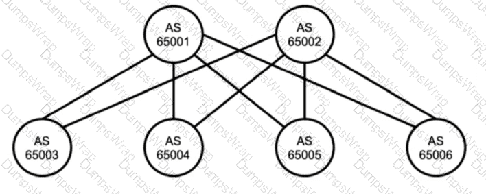
Referring to the exhibit, which two statements are true about BGP? Choose two.
Options:
The exhibit uses IBGP.
Devices should peer using loopback addresses.
The exhibit uses EBGP.
Devices should peer using physically connected IP addresses.
Answer:
C, DExplanation:
The diagram shows multiple autonomous systems, with each device labeled with a different AS number. Because the peers are in different autonomous systems, the correct BGP session type is external BGP. In a typical Juniper data center IP fabric underlay, this design is intentional: EBGP is used between leaf and spine devices to simplify policy boundaries, improve operational clarity, and avoid the additional mechanisms commonly required in large internal BGP designs.
In an EBGP-based underlay, neighbors are most commonly formed over the directly connected point-to-point links between leaf and spine. That means the BGP peering is established using the IP addresses configured on those physical routed interfaces, not loopback addresses. Using physically connected addresses aligns with the default EBGP behavior where the TTL is one hop, and it reduces configuration complexity because no multihop settings or additional reachability dependencies are required to bring up the session.
Peering using loopbacks is possible, but it typically requires EBGP multihop and a routing method to ensure reachability to the remote loopback before BGP can establish. That approach is more common for overlay control-plane sessions or for specific design requirements, rather than for the simplest and most common underlay implementation. Therefore, the two true statements are that the exhibit uses EBGP and that devices should peer using physically connected IP addresses.
Which statement is correct about access ports?
Options:
They are assigned to a single VLAN.
They are assigned to multiple VLANs.
They must be connected to a router.
They must be connected to a firewall.
Answer:
AExplanation:
An access port is a Layer 2 switch interface mode intended for an endpoint that belongs to a single VLAN. Traffic on an access port is associated with exactly one VLAN, and frames are typically transmitted and received untagged on the wire. The switch internally maps that untagged traffic into the configured access VLAN, placing the endpoint into the correct broadcast domain. This behavior is widely used for server access, management ports, out of band devices, and any endpoint that does not tag VLANs.
By contrast, trunk ports are designed to carry multiple VLANs simultaneously, usually with 802.1Q tagging, and are typically used between switches, to routers, to virtualization hosts, or to appliances that handle multiple VLANs. That is why assigning multiple VLANs to an access port is not the standard access mode behavior.
An access port does not have to connect to a router or a firewall. It can connect directly to any Ethernet endpoint. Routing between VLANs is provided by a Layer 3 interface such as an IRB interface on the switch or an external routed device, but that is independent of whether the endpoint connects on an access port.
Verification sources from Juniper documentation
https://www.juniper.net/documentation/us/en/software/junos/multicast-l2/topics/task/interfaces-configuring-ethernet-switching-access.html
You want to enable routing between VLAN 10 and VLAN 20.
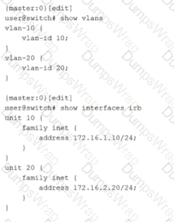
Which two configuration statements must be included in the configuration shown in the exhibit to accomplish this task? Choose two.
Options:
set vlans default vlan-id 20
set vlans vlan-10 l3-interface irb.10
set vlans vlan-20 l3-interface irb.20
set vlans default vlan-id 10
Answer:
B, CExplanation:
Inter-VLAN routing on Junos switching platforms is typically implemented by associating each VLAN or bridge domain with an IRB interface that provides the Layer 3 gateway for that VLAN. In the exhibit, VLAN 10 and VLAN 20 are defined with vlan-id values, and IRB logical units 10 and 20 already have IPv4 addresses assigned. However, the VLAN definitions do not yet reference the IRB interfaces. Without that association, hosts in the VLANs have no routed gateway on the switch, and the switch cannot perform Layer 3 forwarding between the two VLAN subnets.
To enable routing, each VLAN must include an l3-interface statement that binds the VLAN to the corresponding IRB logical unit. Adding l3-interface irb.10 under vlan-10 makes irb.10 the default gateway interface for VLAN 10 and enables the device to route traffic sourced from that VLAN. Adding l3-interface irb.20 under vlan-20 does the same for VLAN 20. Once both VLANs are bound to their IRB interfaces, the switch can route packets between 172.16.1.0/24 and 172.16.2.0/24 using its routing table, while still switching Layer 2 traffic within each VLAN.
The default VLAN settings are unrelated to enabling routing between these two specific VLANs. They control the behavior of the default VLAN, not the creation of Layer 3 gateways for VLAN 10 and VLAN 20.