
Enterprise Routing and Switching, Specialist (JNCIS-ENT) Questions and Answers
[Exhibit]
Click the Exhibit button.
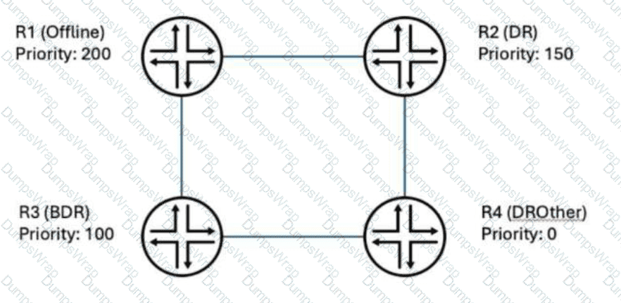
An OSPF broadcast segment has four routers with roles as shown in the exhibit. R1 is currently offline, and default OSPF settings are in place.
In this scenario, what happens when R1 comes back online?
Options:
DR roles do not change; R1 becomes DROther.
R1 becomes the DR and R2 becomes the BDR.
R1 becomes the DR and R3 remains the BDR.
R1 cannot join the OSPF area until the current DR (R2) is restarted.
Answer:
AExplanation:
OSPF's Designated Router election, as defined in RFC 2328 and implemented unchanged in Junos, is explicitly non-preemptive. Router priority is used only at the moment an election actually takes place — that is, when no DR or BDR currently exists on the segment. Once a DR and BDR have been elected and are functioning, a router with a numerically higher priority that joins the segment afterward does not trigger a new election and does not displace the incumbent DR or BDR, no matter how much higher its priority value is. In this scenario, R2 (priority 150) and R3 (priority 100) were already elected DR and BDR respectively while R1 was offline. When R1, whose priority of 200 would have made it the preferred DR had it been present during the original election, returns to the segment, it simply forms a full adjacency with the existing DR and BDR and takes on the DROther role like R4, without any re-election occurring. This design choice exists specifically to prevent unnecessary and disruptive Network LSA regeneration and adjacency churn every time a high-priority router reboots or rejoins a stable broadcast network. The only ways R1 could become DR going forward are if the current DR fails (promoting the BDR to DR and triggering a new BDR election) or if the entire segment's OSPF process is restarted, forcing a fresh election from a clean state. Reference topics: Junos Enterprise Routing – OSPF, Designated Router Election and Non-Preemption.
You are troubleshooting a Layer 2 topology issue in a campus network. The switches are running RSTP. You need to verify which switch is currently acting as the root bridge and identify the root port on the local device.
Which operational command should the administrator use to view this information?
Options:
show spanning-tree interface
show spanning-tree bridge
show ethernet-switching table
show ethernet-switching interface
Answer:
BExplanation:
The show spanning-tree bridge command is specifically designed to surface exactly the two pieces of information required in this scenario within a single output. Its Root ID field reports the full Bridge Identifier (priority and MAC address) of whichever switch has been elected root bridge for the spanning-tree instance in question, immediately answering which switch in the campus network is currently acting as root, regardless of whether that happens to be the local device or a remote one. In the same output, the command's Root port field explicitly names the specific local interface (for example, ge-0/0/1.0) that the local switch has selected as its path toward that root bridge, directly answering the second part of the requirement without needing to cross-reference a separate command. Together, these two fields give a complete, immediate picture of both root bridge identity and local root port selection from one operational command. show spanning-tree interface instead presents a per-interface breakdown of STP role (root, designated, alternate, backup) and state across all local ports, which can indirectly reveal the root port by looking for the 'Root' role, but it does not directly report the Root ID/root bridge identity in the same structured way that show spanning-tree bridge does. show ethernet-switching table and show ethernet-switching interface pertain entirely to MAC address learning and switching-specific interface configuration respectively, and neither surfaces any spanning-tree topology or root bridge information at all. Reference topics: Junos Enterprise Switching – Spanning Tree Protocols, Verifying Root Bridge and Root Port with show spanning-tree bridge.
Refer to Exhibit:
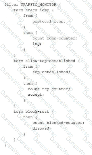
You have applied a firewall filter as an ingress filter on the ge-0/0/0 interface of your Juniper Networks EX Series Switch as shown in the exhibit. An external host sends an ICMP ping packet to the router.
Which statement is correct about how this packet is processed?
Options:
The icmp-counter and blocked-counter are both incremented and the packet is dropped.
The icmp-counter is incremented and the packet is dropped.
The icmp-counter is incremented and the packet is accepted.
The icmp-counter and tcp-counter are both incremented and the packet is accepted.
Answer:
AExplanation:
Junos firewall filters evaluate terms sequentially from top to bottom, and a term is only terminal for a packet if its then clause contains an explicit terminating action such as accept, discard, reject, or next term without a match. The count and log actions used in track-icmp are non-terminating; they update statistics and generate a log entry but do not stop evaluation, so a matching ICMP packet falls through to the next term after being counted. The second term, allow-tcp-established, matches only TCP packets carrying the ACK or RST flags as defined by the tcp-established keyword; an ICMP echo request does not satisfy protocol tcp, so this term is skipped entirely and does not accept the packet. Evaluation therefore reaches the implicit catch-all term block-rest, which has no from conditions and matches every remaining packet, incrementing blocked-counter and discarding it. The net effect for the described ICMP ping is that icmp-counter is incremented by the first term, the packet is neither accepted nor rejected by the second term, and blocked-counter is incremented immediately before the packet is silently discarded by the final term. This layered-term behavior, where counting is independent of the accept/discard decision, is a frequently tested nuance of Junos firewall filter processing logic. Reference topics: Junos Enterprise Switching – Layer 2 Security and Firewall Filters, Filter Term Evaluation Order.
[Exhibit]
Click the Exhibit button.
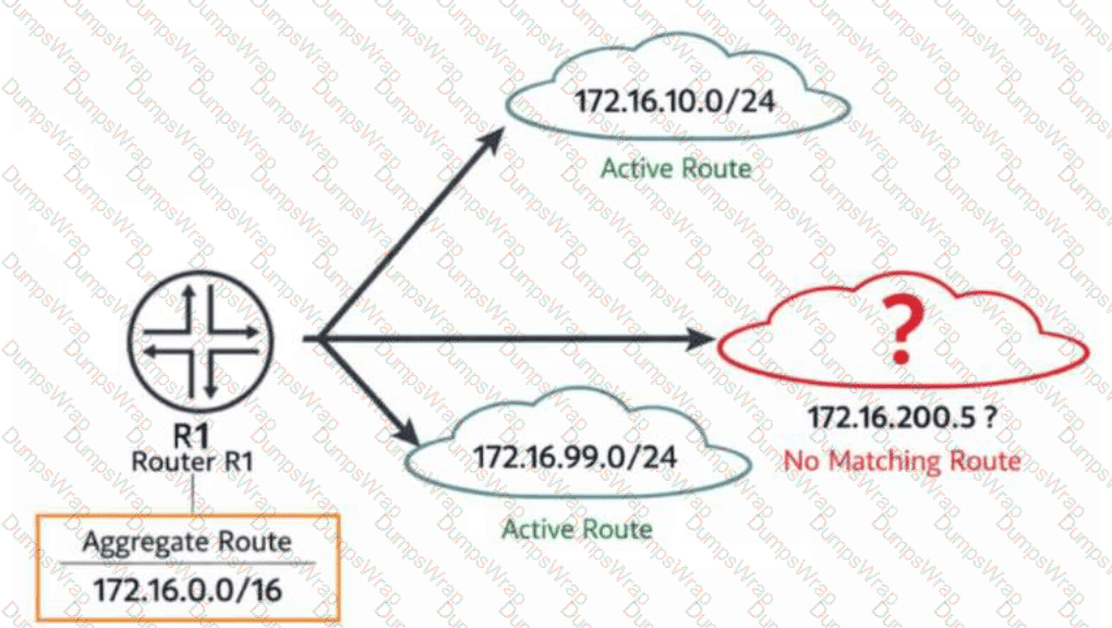
You configure the aggregate route 172.16.0.0/16 on router R1. The routing table currently contains active routes for 172.16.10.0/24 and 172.16.99.0/24. No other more-specific routes exist.
Referring to the exhibit, which statement describes what R1 would do with traffic destined to 172.16.200.5?
Options:
R1 forwards the packet to the default route.
R1 drops the packet and deactivates the aggregate route.
R1 drops the packet and sends an ICMP unreachable message.
R1 forwards the packet using the next hop of the active contributing route.
Answer:
CExplanation:
The destination address 172.16.200.5 falls within the 172.16.0.0/16 aggregate's summarized range but does not fall within either of the two active, more-specific contributing routes actually present in the table — 172.16.10.0/24 and 172.16.99.0/24 — meaning no route more specific than the /16 itself exists to cover it. Under Junos's longest-match forwarding logic, the lookup for 172.16.200.5 therefore resolves to the aggregate route itself, and since aggregate routes are installed by default with a reject next hop rather than any real forwarding path, the router drops the packet and simultaneously generates an ICMP destination-unreachable message back to the originating source, explicitly signaling that no valid path exists for that specific destination even though a covering summary is being advertised. This reject behavior is precisely why aggregate routes are valuable for reducing the number of routes advertised upstream while still providing clear, immediate feedback for traffic aimed at address space within the summary that has no genuine underlying route, rather than silently black-holing it or misdirecting it toward an unrelated contributing route's next hop. The aggregate route itself remains active and installed throughout this process — a gap in contributing coverage does not deactivate the aggregate, since the aggregate's activation depends only on at least one contributing route being active, which is satisfied here by both existing /24 blocks. There is also no default route present in this scenario to fall back upon. Reference topics: Junos Enterprise Routing – Protocol Independent Routing, Aggregate Route Reject Behavior for Uncovered Address Space.
A GRE tunnel is experiencing fragmentation issues. You confirm that the tunnel is up and is functioning correctly. You confirm that hosts are sending 1500-byte packets.
In this scenario, which statement is correct?
Options:
You should use the clear-dont-fragment parameter to allow fragmentation.
You should lower the physical interface's MTU to 1476 bytes to avoid fragmentation.
You should enable BFD to more rapidly identify tunnel link failures.
You should use ToS copying to reduce header size.
Answer:
BExplanation:
GRE encapsulation adds a fixed 24 bytes of overhead to every packet it carries — 4 bytes for the GRE header itself and 20 bytes for the new outer IPv4 delivery header. When a host transmits a full 1500-byte Ethernet payload into a gr- interface, the resulting encapsulated packet becomes 1524 bytes, which exceeds the physical interface's standard 1500-byte MTU and forces fragmentation or drops if the don't-fragment bit is set. The correct remediation is to reduce the effective MTU seen by end hosts so that encapsulated packets never exceed the physical link's transmission limit. Junos automatically applies this logic to gr- logical interfaces, which default to a 1476-byte protocol MTU (1500 minus 24), but when the underlying physical interface or a manually configured path is involved, administrators must explicitly size the interface MTU to 1476 bytes to prevent post-encapsulation oversize packets. Allowing fragmentation with clear-dont-fragment is a workaround that increases CPU load and can degrade performance rather than solving the root cause, BFD addresses link-failure detection rather than MTU sizing, and ToS copying affects only the type-of-service byte, not packet length. Reference topics: Junos Enterprise Routing – Tunneling, GRE Encapsulation and MTU Considerations; Junos OS Configuring GRE Tunnel Interfaces.
[Exhibit]
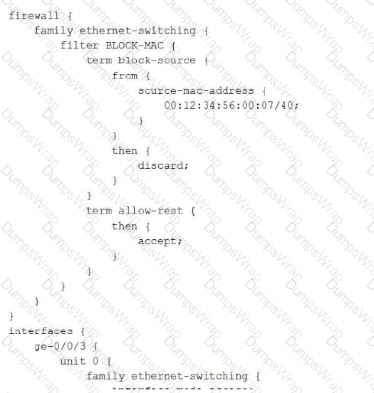
You need to apply a Layer 2 firewall filter on a Juniper Networks EX Series Switch to block traffic from the source MAC address 00:12:34:56:00:07 entering the switch on ge-0/0/3. After committing the configuration, traffic from the MAC address still passes through.
Referring to the exhibit, which statement is correct in this scenario?
Options:
The filter is applied in the wrong direction.
The MAC address and mask in the firewall filter need to be explicit.
The interface needs to be of type trunk for the filter to evaluate correctly.
Firewall filters under family ethernet-switching cannot match on MAC addresses.
Answer:
BExplanation:
The intent of this filter is to match and discard traffic from one single, specific host MAC address, which requires the source-mac-address match condition to reference the complete, exact 48-bit address using an explicit /48 mask (or no mask at all, which Junos treats as an implicit full match) so that only that one precise address is matched. As configured, the term instead specifies a /40 mask on 00:12:34:56:00:07, meaning only the first 40 bits (the first five octets, 00:12:34:56:00) are actually significant to the match, while the sixth octet is effectively wildcarded across its full range; this produces an imprecise, overly broad match criterion rather than the single-host match the administrator intended, and is a common configuration mistake that undermines the predictability and correctness of MAC-based filtering. The lesson tested here is that source and destination MAC address match conditions in Junos firewall filters must be specified with the correct, deliberate, and explicit prefix length appropriate to the intended scope — typically /48 for a single exact host — rather than an arbitrary or miscalculated mask value. Firewall filters under family ethernet-switching are fully capable of matching on both source-mac-address and destination-mac-address, which rules out that option entirely. Layer 2 MAC-based filters function correctly on both access and trunk interface modes, so interface type is not a limiting factor here. There is no indication in the exhibit that the filter's application direction (input versus output) is reversed. Reference topics: Junos Enterprise Switching – Layer 2 Security, MAC Address Match Conditions and Prefix Length Precision.
[Exhibit]
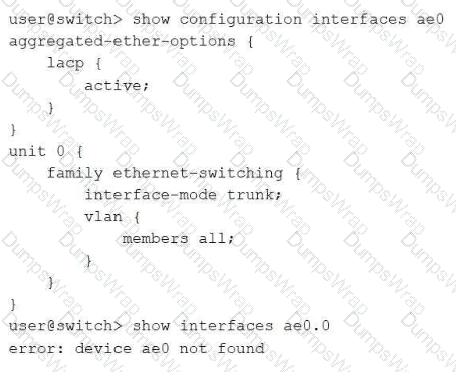
Click the Exhibit button.
You are troubleshooting an aggregated Ethernet interface on a Juniper Networks EX Series Switch. The aggregated Ethernet interface does not appear in the output shown in the exhibit.
Which action will solve this problem?
Options:
Configure the number of aggregated Ethernet devices under the [edit chassis] hierarchy.
Install the aggregated Ethernet interface license on the switch.
Restart the switch to enable the aggregated Ethernet switching process.
Configure LACP passive-mode.
Answer:
AExplanation:
On EX Series switches, aggregated Ethernet (ae) interfaces do not exist by default; before any ae interface can be created, referenced, or brought into service, an administrator must first reserve the desired number of aggregated Ethernet device slots by configuring set chassis aggregated-devices ethernet device-count number at the [edit chassis] hierarchy. This statement allocates the internal resources needed for that many ae interfaces to exist as valid, configurable objects; until it is committed, any interface-level configuration referencing ae0 (such as the aggregated-ether-options and family ethernet-switching stanzas shown in the exhibit) is accepted syntactically by the CLI but never actually instantiates a live ae0 device, which is exactly why show interfaces ae0.0 returns 'device ae0 not found' despite the interface appearing fully configured. Increasing the device-count to at least 1 (or higher, to cover the number of LAG bundles planned) immediately resolves this and allows ae0 to appear as an operational interface once its member links are also associated with it. This is a foundational and frequently overlooked prerequisite step in LAG deployment on Juniper switches. There is no separate licensing requirement for aggregated Ethernet functionality on EX Series switches, a reboot is not needed since the chassis statement takes effect upon commit, and the LACP mode (active versus passive) is unrelated to whether the ae interface object itself exists in the first place. Reference topics: Junos Enterprise Switching – Link Aggregation, Configuring the Aggregated Ethernet Device Count.
Which sequence correctly describes the basic message flow that leads to a successful BGP peering session?
Options:
Idle - > Connect - > OpenConfirm - > OpenSent - > Active - > Established
Idle - > Connect - > Active - > OpenSent - > OpenConfirm - > Established
Connect - > Active - > Idle - > OpenSent - > OpenConfirm - > Established
Connect - > Active - > Idle - > OpenConfirm - > OpenSent - > Established
Answer:
BExplanation:
RFC 4271 defines the BGP finite state machine as a strict, ordered progression of six states that a session must move through to successfully establish. A newly configured or reset session always begins in Idle, where BGP initializes resources and refuses connections until the ConnectRetry timer fires. From Idle, the router transitions to Connect and attempts to establish the underlying TCP transport session to the configured peer address on port 179. If that TCP attempt does not immediately succeed, the session falls back to the Active state, where the router continues retrying the TCP connection in the background; once the TCP handshake finally completes (from either Connect or Active), the session advances to OpenSent, during which the router transmits its own BGP OPEN message advertising its AS number, hold time, BGP identifier, and capabilities. Upon receiving and validating a compatible OPEN message from the peer, the session moves to OpenConfirm, where both sides exchange KEEPALIVE messages to confirm the parameters negotiated in the OPEN exchange are mutually acceptable. Only after this confirmation does the session reach Established, the final state in which UPDATE messages carrying actual routing information begin to flow between the peers. Any deviation from this Idle → Connect → Active → OpenSent → OpenConfirm → Established ordering, as presented in the other answer choices, does not reflect the standardized BGP state machine. Reference topics: Junos Enterprise Routing – BGP, The BGP Finite State Machine.
You are deploying a Juniper Networks EX Series Switch to connect 24 end devices to VLAN 70, with an uplink interface to a distribution switch that carries VLANs 30, 50, and 70. You need to correctly configure the interface type for the end-device interfaces.
In this scenario, which statement is correct?
Options:
Use trunk mode with VLAN 70 set as the native VLAN.
No configuration is needed since VLAN 70 is the highest VLAN-ID.
Use trunk mode with VLAN 70 as the only allowed VLAN.
Use access mode and assign the interfaces to VLAN 70.
Answer:
DExplanation:
Each of the 24 end-device-facing interfaces in this scenario needs to carry traffic for exactly one VLAN, and the end devices themselves are ordinary hosts that neither expect nor generate 802.1Q-tagged frames. This is precisely the definition of an access port in Junos: family ethernet-switching interface-mode is set to access, and a single vlan members statement assigns the port to VLAN 70. Access mode ensures frames egressing toward the host are untagged and any frames received are implicitly treated as belonging to the configured VLAN, which is both simpler to manage and more efficient than trunking, since access ports do not carry the 802.1Q tag overhead nor process VLAN pruning logic relevant only to multi-VLAN links. Trunk mode, by contrast, is reserved for switch-to-switch or switch-to-router links that must simultaneously carry frames for multiple VLANs, such as the uplink toward the distribution switch that transports VLANs 30, 50, and 70 together — configuring the 24 host-facing ports as trunks (with or without a native VLAN) would be functionally incorrect and operationally wasteful, since end devices have no need to interpret VLAN tags. There is also no such behavior in Junos where VLAN-ID numeric value dictates default port behavior, making the 'no configuration needed' option a distractor with no basis in EX Series switching architecture. Reference topics: Junos Enterprise Switching – VLANs, Configuring Access and Trunk Port Modes.
You are required to ensure that Switch 1 will always be designated as the root bridge when participating in your switched network.
What do you need to do to satisfy this requirement?
Options:
Ensure Switch 1 has the highest system MAC address.
Ensure Switch1 has the lowest bridge priority of all the other switches.
Ensure Switch1 has the lowest port priority of all other switches.
Ensure Switch1 has the highest port costs of all the other switches.
Answer:
BExplanation:
Because root bridge election is decided primarily by comparing bridge priority values — with the switch advertising the numerically lowest priority always winning, and MAC address serving only as a fallback tiebreaker when priorities are tied — the only deterministic, reliable way to guarantee that a specific switch is elected root regardless of any other switch's hardware characteristics is to explicitly configure that switch with a lower bridge priority than every other participating switch in the topology. Relying on MAC address alone, as the first distractor suggests, is fundamentally unreliable: MAC addresses are burned in at the factory, cannot be predicted or controlled by the administrator, and any future hardware replacement or newly introduced switch with a numerically lower MAC address could unexpectedly seize the root role since MAC comparison only comes into play at equal priority in the first place, meaning a 'highest MAC' strategy does not even align with how the tiebreak actually favors the lowest value. Port priority and port cost are entirely separate STP parameters that influence which port on a non-root switch is selected as its root port, or which port is selected as designated versus blocking on a given segment; neither parameter has any bearing whatsoever on which switch is elected root bridge for the whole topology, since that decision is made purely from the Bridge ID comparison, independent of any per-port settings. Explicitly and deliberately lowering Switch 1's configured bridge priority is the only correct, industry-standard method. Reference topics: Junos Enterprise Switching – Spanning Tree Protocols, Guaranteeing Root Bridge Placement via Bridge Priority.
Which statement describes the purpose of an integrated routing and bridging (IRB) interface on a Juniper Networks EX Series Switch?
Options:
It removes the need for routing instances.
It performs Layer 2 switching across multiple VLANs.
It provides a Layer 3 gateway for a specific VLAN.
It replaces the need for trunk ports.
Answer:
CExplanation:
An integrated routing and bridging interface, configured as irb.x on an EX Series switch, is the mechanism that bridges the Layer 2 and Layer 3 forwarding planes for a given bridge domain or VLAN. By assigning an irb logical unit to a VLAN and configuring an IP address on that unit, the switch gains a routable Layer 3 gateway address that hosts within that VLAN can use as their default gateway, enabling traffic destined for other subnets to be routed off the local broadcast domain. Internally, when a frame destined for the gateway's MAC address arrives on any port belonging to that VLAN, the switch's integrated circuitry hands the packet from the Layer 2 bridging domain to the Layer 3 routing engine associated with the corresponding irb interface, and vice versa for the return path — hence the name 'integrated routing and bridging.' IRB does not eliminate the need for routing instances, which remain a separate mechanism for isolating routing tables; it does not itself perform inter-VLAN switching, since switching still happens strictly within a VLAN's own broadcast domain; and it has no relationship to trunk ports, which remain necessary for carrying multiple tagged VLANs between switches. IRB is the standard method for enabling inter-VLAN routing on a single EX Series switch without an external router. Reference topics: Junos Enterprise Switching – Routing VLANs, Configuring Integrated Routing and Bridging.
You have traffic for a video streaming application traversing a GRE tunnel in your network and users are reporting poor performance. Both ends of the tunnel are using the default settings for a gigabit Ethernet interface, but you observe excessive packet drops due to exceeding the MTU.
Which two steps would you take to improve connectivity for this application? (Choose two.)
Options:
Increase the MTU for the member interfaces to 1524 bytes.
Route the GRE tunnel through a higher bandwidth link.
Configure the clear-dont-fragment option on the member interfaces.
Increase the MTU for the member interfaces to 1500 bytes.
Answer:
A, CExplanation:
The described symptom — excessive packet drops specifically attributed to exceeding the MTU on a GRE tunnel carrying full-size video streaming traffic across default-MTU gigabit Ethernet interfaces — is a direct consequence of the 24 bytes of GRE encapsulation overhead pushing packets that were already at or near the standard 1500-byte Ethernet MTU past the physical interface's transmission limit once the outer GRE and IP headers are added. The most durable fix is to proactively increase the physical member interfaces' MTU beyond the 1500-byte default — to 1524 bytes or higher — which provides sufficient headroom to absorb the full GRE encapsulation overhead without ever causing the fully encapsulated packet to exceed the interface's transmission capability, allowing full-size 1500-byte payloads to pass through the tunnel intact and without fragmentation or drops. As a complementary measure, configuring the clear-dont-fragment-bit option on the tunnel or member interfaces instructs Junos to clear the DF (don't fragment) bit on oversized packets rather than dropping them outright when they do exceed the available MTU, allowing the Packet Forwarding Engine to fragment and later reassemble the traffic instead of silently discarding it, which directly addresses the reported packet loss even under transient conditions. Simply raising the MTU only to 1500 bytes fails to account for the 24-byte GRE overhead and would not resolve the underlying oversize condition. Routing the tunnel over a higher-bandwidth link addresses potential congestion but does nothing to correct an MTU-based packet-size violation, which is the root cause explicitly identified in this scenario. Reference topics: Junos Enterprise Routing – Tunneling, GRE MTU Sizing and Fragmentation Handling for High-Throughput Applications.
A host connected to interface ge-0/0/3 on your Juniper Networks EX Series Switch cannot reach another device in the same VLAN. The administrator wants to confirm that the switch has learned the MAC address of the host.
Which command should be used to accomplish this task?
Options:
show ethernet-switching table
show interfaces terse
show vlans
show interfaces extensive
Answer:
AExplanation:
The show ethernet-switching table command displays the Layer 2 forwarding database (the bridge or MAC table) that an EX Series switch builds dynamically by inspecting the source MAC address of every frame it receives. Each entry records the learned MAC address, the VLAN it was learned on, the type of entry (dynamic, static, or persistent), and the specific interface through which that address was seen, which is precisely the information needed to confirm whether the switch has learned the host connected to ge-0/0/3. If the host's MAC address is absent from the table, that immediately points to a Layer 1/2 issue — no frames have been received from the host, a cabling or port problem exists, or the interface is administratively down or blocked by spanning tree — rather than a Layer 3 routing or VLAN membership problem. show interfaces terse only reports administrative and link state along with any assigned protocol family addresses, offering no MAC-learning visibility. show vlans lists VLAN definitions and their member interfaces but does not display learned host addresses. show interfaces extensive provides detailed physical-layer counters and error statistics, useful for diagnosing frame loss or interface errors, but it does not expose the switching table. For intra-VLAN reachability troubleshooting, verifying MAC learning is always the first and most direct Layer 2 checkpoint. Reference topics: Junos Enterprise Switching – Layer 2 Switching Fundamentals, Monitoring the Ethernet Switching Table.
Your router receives two BGP routes for the same prefix. One route is learned from an IBGP neighbor, and the other route is learned from an EBGP neighbor.
By default, which route will be selected as active in this scenario?
Options:
The route learned through IBGP.
The route learned with the highest next-hop IP address.
The route with the shortest AS-path.
The route learned from the neighbor with highest router ID.
Answer:
CExplanation:
Once the two candidate routes have equal route preference and equal local preference (both defaulting to 100 unless modified by policy), the Junos BGP algorithm proceeds to its third decision step, which compares the length of each candidate's AS path attribute and selects whichever path carries the shortest AS path, since a shorter path is interpreted as traversing fewer autonomous system hops to reach the origin. This step occurs well before the algorithm ever reaches the specific EBGP-over-IBGP preference rule, which is only evaluated later, after local preference, AS path length, origin type, and MED have all already been compared and found equal between the candidates; because an IBGP-learned copy of a route typically retains the identical AS path that was originally received from the external AS (IBGP does not prepend the local AS number the way crossing an AS boundary does), it is entirely possible, and often the deciding scenario, for AS path length to differ between competing paths well before the algorithm would ever need to fall back on the IBGP-versus-EBGP tiebreak. Selecting a route purely because it was 'learned through IBGP' is not a rule that exists anywhere in the algorithm and would in fact typically be the opposite of Junos's later EBGP-preference tiebreak. Neither next-hop IP address value nor router ID value is compared with a 'highest wins' rule at any point in the standard path selection sequence — where router ID is used at all, Junos prefers the lowest value, not the highest, making both of those distractors doubly incorrect. Reference topics: Junos Enterprise Routing – BGP, Path Selection Order: AS Path Length Precedes EBGP/IBGP Preference.
Which statement is correct about how a Juniper Networks EX Series Switch learns MAC addresses?
Options:
The switch adds destination MAC addresses to the bridge table after forwarding frames.
The switch learns MAC addresses by polling connected hosts periodically.
The switch learns MAC addresses only after a spanning-tree topology change occurs.
The switch learns source MAC addresses from received frames and records the ingress interface and timestamp.
Answer:
DExplanation:
Layer 2 MAC learning on an EX Series switch, as on any standard Ethernet bridge, is a passive, frame-driven process rather than an active polling or query-based mechanism. Every time a frame arrives on any interface, the switch inspects the frame's source MAC address field and, if that address is not already present in the Ethernet switching (bridge) table for the associated VLAN, creates a new dynamic entry recording the source MAC address, the VLAN it was learned on, and the specific ingress interface through which the frame arrived. Junos also stamps each learned entry with an aging timestamp, which is refreshed every time a subsequent frame from that same source MAC is received; entries that receive no refreshing traffic within the configured MAC aging interval (300 seconds by default) are eventually purged from the table to keep it current and to reclaim table space from hosts that have moved or gone offline. This source-address-driven, per-frame learning process happens continuously and automatically with no dependency on spanning-tree state changes — although a topology change notification can trigger accelerated aging of the table to flush potentially stale entries faster, learning itself is not gated by or contingent upon such an event occurring. The switch never learns addresses from the destination field of a frame, since the destination address, if already known, is used purely for the forwarding lookup decision, not for populating new table entries. Reference topics: Junos Enterprise Switching – Layer 2 Switching Fundamentals, Source MAC Learning and Table Aging.
Which IS-IS TLV should be used to advertise information about the router's neighbors and link metrics?
Options:
TLV 22
TLV 2
TLV 132
TLV 129
Answer:
AExplanation:
TLV 22, the Extended IS Reachability TLV defined in RFC 5305, is the modern and Junos-preferred mechanism for advertising a router's adjacent neighbors together with the metric associated with each link. It carries the seven-octet system ID and pseudonode number of each neighbor along with a 24-bit wide metric field, and supports an extensible set of sub-TLVs used for traffic-engineering data such as interface and neighbor IP addresses, bandwidth, and administrative groups. The original IS Reachability TLV, TLV 2, defined in the base ISO 10589 standard, carries similar neighbor and metric information but is constrained to a 6-bit narrow metric with a maximum value of 63, which is inadequate for expressing meaningful cost differentiation in modern, high-capacity enterprise and service-provider topologies; consequently, Junos deployments are commonly configured for wide-metrics-only, favoring TLV 22 over the legacy TLV 2 whenever traffic-engineering-capable or simply more granular metric representation is desired. TLV 132, the IP Interface Address TLV, only advertises the IPv4 addresses configured on the originating router's interfaces and carries no neighbor-adjacency or metric information. TLV 129, the Protocols Supported TLV, merely lists which network-layer protocols (such as IPv4 or IPv6) the originating router is capable of routing, and likewise has nothing to do with neighbor reachability or link cost. Reference topics: Junos Enterprise Routing – IS-IS, Extended IS Reachability and Wide Metrics.
What are three valid OSPF adjacency states? (Choose three.)
Options:
reject
loading
down
established
init
Answer:
B, C, EExplanation:
OSPF neighbor state progression, as defined in RFC 2328 and displayed by Junos through show ospf neighbor, moves through a well-defined set of named states: Down, Attempt, Init, 2-Way, ExStart, Exchange, Loading, and Full. Down is the initial state, indicating no Hello packets have been recently received from a potential neighbor on that interface; it is a genuine, valid OSPF state and is correctly included here. Init indicates that a Hello packet has been received from the neighbor, but that neighbor has not yet listed the local router's own router ID within its Hello packet, so bidirectional communication has not yet been confirmed; this too is a standard, valid state. Loading occurs after the Exchange state, during which Database Description packets have been fully exchanged and the router is now actively requesting the specific, more-detailed LSAs it identified as missing or outdated from its neighbor via Link State Request packets; it is likewise a standard, valid OSPF neighbor state. 'Established' is not an OSPF state at all — that terminology belongs to BGP's finite state machine, where Established represents the fully operational session state; the OSPF equivalent concept is instead called Full. 'Reject' is not a recognized OSPF neighbor state under any circumstance and does not appear anywhere in the RFC 2328 state machine, making it an invalid distractor as well. Reference topics: Junos Enterprise Routing – OSPF, The OSPF Neighbor State Machine.
A switch uses the factory-default storm control configuration. A sudden unknown-unicast burst causes packet loss for only 4-5 seconds before stabilizing.
Which statement describes why normal operation resumes automatically?
Options:
Storm control applies only to multicast traffic by default.
Storm control triggers GRES recovery.
Storm control shuts down the interface and re-enables it after 5 seconds.
Storm control drops only excess packets until traffic falls below the threshold.
Answer:
DExplanation:
The factory-default storm control configuration on EX Series switches operates in a purely rate-limiting mode rather than an interface-shutdown mode. When broadcast, multicast, or unknown-unicast traffic on a port exceeds the configured bandwidth-percentage threshold, the default action is simply to police the offending traffic type and silently drop only the packets that exceed that threshold, while all traffic within the allowed rate continues to be forwarded normally and the interface itself remains administratively and operationally up throughout the event. This explains the observed symptom precisely: during the burst of unknown-unicast frames, the switch dropped the excess volume above the configured limit, producing a brief period of packet loss, but as soon as the burst subsided and traffic fell back under the threshold, storm control simply stopped dropping packets and normal forwarding resumed automatically — no administrative shutdown, recovery timer, or manual intervention was ever involved, because the interface was never taken down in the first place. This default drop-only behavior is distinct from the optional interface-shutdown action, which must be explicitly configured if an administrator wants storm control to disable a port outright on violation (as seen in a related scenario requiring the clear ethernet-switching recovery-timeout command). Storm control by default covers broadcast, multicast, and unknown-unicast traffic types together, not multicast alone, and it has no functional relationship to GRES, which governs Routing Engine redundancy rather than Layer 2 traffic policing. Reference topics: Junos Enterprise Switching – Storm Control, Default Drop Behavior Versus Interface Shutdown Action.
How would you view the metric assigned to a route in OSPF? (Choose two.)
Options:
Use the show route protocol ospf command.
Use the show ospf route intra command.
Use the show ospf database extensive command.
Use the show ospf interface command.
Answer:
A, BExplanation:
The metric that OSPF assigns to a destination is visible from two complementary vantage points in Junos. The show route protocol ospf command displays the main routing table filtered to OSPF-learned prefixes, and each entry shows the computed cost alongside the next hop, exactly as it was installed after SPF calculation. The show ospf route command (which accepts filters such as intra-area, inter-area, and extern) presents the OSPF-specific routing table, organized by route type, and explicitly lists the metric column for every intra-area, inter-area, and external route the local router has calculated. Together these two commands give both the RIB-level and the protocol-level view of route cost. By contrast, show ospf database extensive dumps the raw link-state advertisements, where metrics appear only as link-level values buried inside Router or Network LSAs rather than as a resolved route cost, so it is not the direct tool for viewing a route's metric. show ospf interface reports interface operational state, area, and DR/BDR information but does not present a cost or metric field at all in its standard output. Candidates should be comfortable distinguishing the RIB-oriented and protocol-table-oriented verification commands, since JNCIS-ENT scenarios frequently test whether a candidate reaches for the correct show command layer during troubleshooting. Reference topics: Junos Enterprise Routing – OSPF Operation and Verification, Monitoring OSPF.
