Service Provider Routing and Switching - Specialist (JNCIS-SP) Questions and Answers
You are configuring BGP for IPv6 operations. In this scenario, which two statements are correct? (Choose two.)
Options:
The Autonomous System Number (ASN) must be a 64-bit value.
The router ID uses a 128-bit identifier value.
The router ID uses a 32-bit identifier value.
The Autonomous System Number (ASN) can be either a 32-bit or 64-bit value.
Answer:
C, DExplanation:
When implementingMultiprotocol BGP (MP-BGP)for IPv6, several architectural constants remain consistent with the original BGP design, while others have evolved to accommodate larger network scales.
Router ID (Option C):
A critical point in Juniper's Service Provider documentation is that theBGP Router IDremains a32-bit value, even when the protocol is carrying 128-bit IPv6 prefixes. The Router ID is typically represented in dotted-quad notation (e.g., 192.168.1.1). In an IPv6-only environment, a Juniper router cannot automatically derive this ID from an interface address, so it must be manually defined under [edit routing-options]. This 32-bit ID is essential for BGP tie-breaking and loop prevention within the AS.
Autonomous System Number (Option D):
TheAutonomous System Number (ASN)was originally a 16-bit value (0 to 65535). However, to address the exhaustion of available ASNs, the standard was extended to32-bit ASNs(documented in RFC 6793). In Junos OS, you can configure BGP using either the older 16-bit format or the newer 32-bit format (often represented in "asplain" or "asdot" notation). While the question mentions a 64-bit value, there is currently no standard for a 64-bit ASN in BGP; the transition from 16-bit to 32-bit satisfies current global scalability needs. Therefore, Option D is the most accurate within the context of current networking standards, as it acknowledges the coexistence of different ASN lengths.
Which two statements about graceful restart are correct? (Choose two.)
Options:
Graceful restart restarting router mode is not enabled by default.
Graceful restart helper mode is enabled by default.
Graceful restart requires that GRES be enabled.
Graceful restart uses nonstop bridging for forwarding operations.
Answer:
A, BExplanation:
Graceful Restart (GR)is a high-availability mechanism designed to minimize the impact of a routing protocol process (rpd) restart or a Routing Engine (RE) switchover. It allows a router to continue forwarding traffic while the control plane is recovering, provided that the data plane (Packet Forwarding Engine) remains intact.
According to Juniper Networks documentation, Graceful Restart operates in two distinct roles:
Restarting Mode:This is the role of the router that is actually undergoing the restart. In Junos OS, this mode isnot enabled by default (Option A). An administrator must explicitly configure graceful-restart under the [edit routing-options] hierarchy to allow the router to signal its neighbors that it is attempting a graceful recovery.
Helper Mode:This is the role of the neighboring routers. When a neighbor sees a router restart, if it is in "helper mode," it will continue to forward traffic toward the restarting router and will not flush the associated routes from its forwarding table for a specified period. In Junos,helper mode is enabled by default (Option B)for most protocols (OSPF, BGP, IS-IS). This means that even if you haven't configured GR on your own router, it will automatically assist its neighbors if they perform a graceful restart.
Why other options are incorrect:
Option C:WhileGRES (Graceful Routing Engine Switchover)is often usedwithGraceful Restart to handle hardware-level RE failures, they are independent features. GR can function during a simple software process restart without dual REs or GRES.
Option D:Nonstop Bridging (NSB)is a separate high-availability feature for Layer 2 protocols (like STP). While it shares a similar goal, Graceful Restart is specifically a Layer 3 protocol mechanism (Layer 2 does not use "helper" routers in the same way).
Exhibit:
user@R2> show route 198.51.100.1
inet.0: 19 destinations, 19 routes (19 active, 0 holddown, 0 hidden)
Restart Complete
+ = Active Route, - = Last Active, * = Both
198.51.100.1/32 *[Static/5] 5d 21:02:26
> to 203.0.113.65 via ge-0/0/3.0
user@R2> show route 172.20.110.0/24
inet.0: 19 destinations, 19 routes (19 active, 0 holddown, 0 hidden)
Restart Complete
+ = Active Route, - = Last Active,
* = Both
172.20.110.0/24 *[Static/5] 10:43:01
> via gr-0/0/0.0
Referring to the exhibit, traffic destined to which network will be sent through the tunnel?
Options:
172.20.110.0/24
203.0.113.65
0.0.0.0/0
198.51.100.1/32
Answer:
AExplanation:
To determine which traffic is being sent through a tunnel in a Junos OS environment, an administrator must analyze the routing table output for the exit interface associated with each destination prefix. The provided exhibit shows the results of the show route command on routerR2for two specific destination networks.
In the first output, the destination198.51.100.1/32is an active static route. The next-hop information specifies that traffic for this address is sent to the gateway 203.0.113.65 via the interfacege-0/0/3.0. According to Juniper Networks interface naming conventions, the prefixge-denotes aGigabit Ethernetinterface, which represents a standard physical connection. Therefore, this traffic does not traverse a tunnel.
In the second output, the destination172.20.110.0/24is also an active static route. However, the next-hop for this network is listed asvia gr-0/0/0.0. In the Junos operating system, thegr-prefix explicitly identifies aGeneric Routing Encapsulation (GRE) tunnel interface. GRE is a widely used protocol in service provider networks to encapsulate various network layer protocols over an IP backbone, effectively creating a virtual point-to-point link. Because the routing table has installed the route for 172.20.110.0/24 specifically via the gr- interface, all traffic destined for this network will be encapsulated and sent through the tunnel.
The other choices are incorrect for the following reasons:
203.0.113.65 (Option B):This is the next-hop IP address for the physical Gigabit Ethernet path; it is not a destination network directed to a tunnel.
0.0.0.0/0 (Option C):There is no information in the exhibit regarding a default route.
198.51.100.1/32 (Option D):As identified by thege-interface prefix in the exhibit, traffic for this destination is sent via a physical Ethernet link.
You are asked to configure a new network environment that will be based on IPv6 and use OSPF. In this scenario, which two statements correctly identify configuration task considerations? (Choose two.)
Options:
Participating interfaces must be configured with both IPv4 and IPv6 protocol families and addresses.
The router ID used must be based on a 128-bit identifier value.
The router ID used must be based on a 32-bit identifier value.
Participating interfaces are only required to be configured with the IPv6 protocol family and address.
Answer:
C, DExplanation:
When transitioning to an IPv6 environment usingOSPFv3(the version of OSPF designed for IPv6), there are significant architectural differences compared to OSPFv2 (IPv4). According to Juniper Networks technical documentation, OSPFv3 was redesigned to be more protocol-agnostic.
Router ID (Option C):
Despite OSPFv3 routing IPv6 (which uses 128-bit addresses), the OSPFRouter IDremains a32-bit valueformatted like an IPv4 address (e.g., 1.1.1.1). This is a common point of confusion. In a pure IPv6 environment where no IPv4 addresses are configured on any interfaces, a Juniper router cannot automatically derive a Router ID. Therefore, the administrator must manually configure a 32-bit Router ID under [edit routing-options] for the OSPFv3 process to initialize.
Interface Configuration (Option D):
OSPFv3 runs directly over the IPv6 link-local scope. Unlike OSPFv2, it does not require an IPv4 address to function. Therefore, interfaces areonly required to be configured with family inet6(Option D). You do not need "dual-stack" (both IPv4 and IPv6) functionality just to run OSPFv3. The protocol uses the link-local address (fe80::/10) of the interface for neighbor adjacencies and as the next hop for routing updates. This separation allows OSPFv3 to carry multiple "address families" (both IPv4 and IPv6 unicast) if needed, but the base requirement for an IPv6-only network is simply the family inet6 configuration.
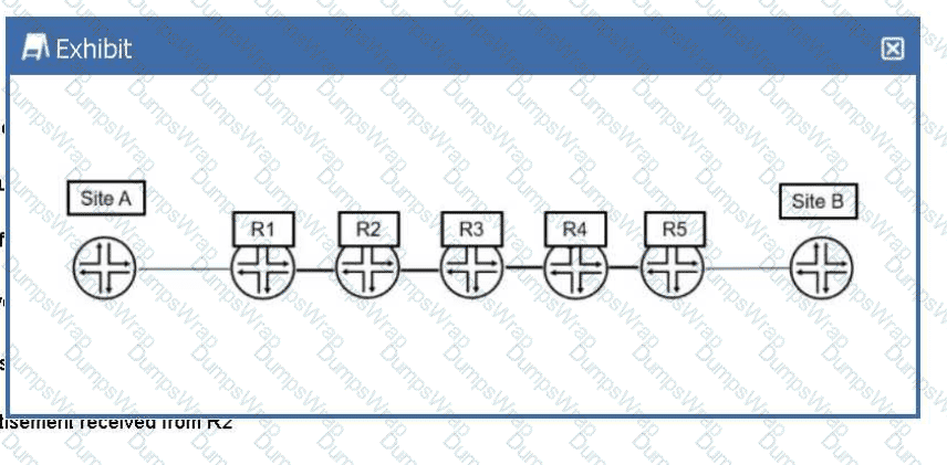
In the exhibit, Site A is sending traffic to Site B. R1 adds MPLS label 7166 to direct the traffic to R5. Which two criteria did R1 use to determine which label number to add to the traffic? (Choose two.)
Options:
the source address of the traffic
a label number received from R5
the destination address of the traffic
a label number advertisement received from R2
Answer:
C, DExplanation:
In a Juniper Networks MPLS environment, the process by which a router determines how to forward traffic involves both the control plane and the data plane. When R1 (acting as an Ingress Label Edge Router, or LER) receives an IP packet from Site A destined for Site B, it must perform a lookup to decide whether to forward the packet via standard IP routing or via an MPLS Label Switched Path (LSP).
The first criterion R1 uses is thedestination address of the traffic(Option C). Upon receiving the native IP packet, R1 looks up the destination IP in its routing table (typically inet.0). If the destination matches a prefix that is associated with an LSP—such as the loopback address of R5 or a prefix reachable via R5—the router identifies the appropriate Forwarding Equivalence Class (FEC). The FEC essentially groups packets that should be forwarded in the same manner over the same path. Without identifying the destination, the router cannot map the traffic to the correct MPLS tunnel.
The second criterion is thelabel number advertisement received from R2(Option D). MPLS relies on downstream label allocation. In this topology, R2 is the immediate downstream "next hop" for R1 on the path to Site B. For the LSP to be established, R2 must signal a label to R1 using a protocol like LDP (Label Distribution Protocol) or RSVP (Resource Reservation Protocol). This label (in this case, 7166) tells R1: "If you want to send traffic to the destination associated with this LSP, wrap it in this specific label so I know how to process it."
R1 does not use the source address (Option A) for standard label mapping, nor does it receive the label directly from R5 (Option B) in a hop-by-hop signaling model; it must use the label provided by its direct neighbor, R2. Therefore, by combining the destination IP (to find the path) and the label provided by the next hop (to encapsulate the packet), R1 successfully directs the traffic through the MPLS core.
You are designing a high availability solution for a Juniper router with dual Routing Engines (RE). You want to ensure that the routing protocol state is preserved during an RE switchover. You have already enabled graceful Routing Engine switchover (GRES) and you want to avoid relying on helper routers to maintain the routing protocol state. In this scenario, which feature would accomplish this behavior?
Options:
non-stop active bridging
bidirectional forwarding detection
graceful restart
non-stop active routing
Answer:
DExplanation:
When designing High Availability (HA) for Juniper Service Provider routers, understanding the interaction between the control plane and data plane is vital. The user has already enabledGraceful Routing Engine Switchover (GRES), which synchronizes the interface and kernel state between the primary and backup Routing Engines (REs). However, GRES by itself does not preserve the routing protocol state (like OSPF adjacencies or BGP sessions).
To achieve the preservation of the routing protocol state without relying on external "helper" routers, you must implementNon-Stop Active Routing (NSR). According to Juniper Networks documentation, NSR uses the infrastructure provided by GRES to also synchronize the routing protocol process (rpd) information. Under NSR, the backup RE maintains a "hot" standby state of all routing protocols. If the primary RE fails, the backup RE takes over immediately. Because it already possesses the full routing table and peer session states, the peering neighbors are unaware that a switchover occurred. No protocol adjacency resets occur, and traffic continues to flow uninterrupted.
It is crucial to differentiate NSR fromGraceful Restart (Option C). While Graceful Restart also aims to maintain traffic flow during a switchover, itdoesrequire help from neighboring routers (known as "helper mode"). If the neighbors do not support or are not configured for Graceful Restart, the sessions will drop. Since the user explicitly stated they want to "avoid relying on helper routers," Graceful Restart is not the correct solution.
Non-stop Active Bridging (Option A)provides a similar "hitless" failover but specifically for Layer 2 environments (STP/VLANs) rather than Layer 3 routing protocols.BFD (Option B)is a failure detection protocol used to speed up convergence but does not preserve state during an RE failover; in fact, without NSR, BFD would likely trigger a faster teardown of the session during a switchover. Therefore,NSRis the only feature that meets the requirement for independent control-plane preservation.
You are configuring LDP in a service provider network. After enabling LDP on core interfaces, you notice that labels are being advertised for every loopback IPv4 address that is in your IGP. Which label distribution mode is being used in this scenario?
Options:
conservative retention
ordered control
downstream unsolicited
downstream on demand
Answer:
CExplanation:
In the context of theLabel Distribution Protocol (LDP), the method by which a router advertises labels to its neighbors is defined by itsLabel Advertisement Mode. According to Juniper Networks documentation and industry standards (RFC 5036), there are two primary modes:Downstream Unsolicited (DU)andDownstream on Demand (DoD).
InDownstream Unsolicited (DU)mode, which is the default behavior for Junos OS and most service provider implementations, an LSR (Label Switching Router) does not wait for a specific request from its neighbors. Instead, as soon as the LSR learns a prefix through its Interior Gateway Protocol (IGP) and establishes an LDP session, it automatically generates a label for that prefix and advertises it to all of its LDP peers. This explains the scenario where labels appear for every loopback address in the IGP as soon as LDP is enabled. DU mode is highly efficient for fast convergence because the labels are already present in the neighbors' databases before they are even needed for traffic forwarding.
By contrast,Downstream on Demand (DoD)requires a router to explicitly request a label for a specific prefix from its next-hop neighbor.Ordered Control (Option B)andIndependent Controlrefer to thetimingof label creation (whether a router waits for the next-hop to provide a label before creating its own), whileConservative Retention (Option A)refers to how a router stores labels it receives but doesn't currently use for forwarding. In the Junos default environment, LDP utilizesDownstream Unsolicitedadvertisement combined withOrdered ControlandLiberal Retentionto ensure a robust and rapidly converging MPLS control plane.
The MPLS Label Information Base (LIB) is stored in which table?
Options:
inet6.0
mpls.0
inet.3
inet.0
Answer:
BExplanation:
In Junos OS, the Routing Engine maintains several different tables to manage various types of reachability and forwarding information. When a router is running MPLS, it must track both IP routes and label-to-label mappings.
Thempls.0table is the primary repository for theLabel Information Base (LIB)and theLabel Forwarding Information Base (LFIB). According to Juniper Networks documentation, mpls.0 is used by transit and egress routers to perform label lookups. When a labeled packet arrives at an interface, the router looks at the top label and references the mpls.0 table to determine the next action. This table stores the mapping of incoming labels to their corresponding operations:Pop(remove the label),Swap(replace the label), orPush(add an additional label).
It is crucial to understand the roles of the other tables to avoid confusion:
inet.0 (Option D):This is the default unicast routing table for IPv4, used for standard IP-to-IP forwarding.
inet.3 (Option C):This is theMPLS Path Table. It stores the egress loopback addresses of LSPs and is used by BGP for next-hop resolution to determine if a destination can be reached via an MPLS tunnel. While inet.3 knowsaboutLSPs, the actual label-switching instructions reside in mpls.0.
inet6.0 (Option A):This is the default unicast routing table for IPv6.
Therefore, for the specific purpose of storing the label base used for transit switching operations,mpls.0is the correct and only table used in the Junos architecture.
What prevents routing loops in a single-area OSPF network?
Options:
The Dijkstra algorithm
Routing policies
The Bellman-Ford algorithm
Forwarding policies
Answer:
AExplanation:
In OSPF, loop prevention within a single area is achieved through the fundamental nature of its link-state architecture. Unlike distance-vector protocols that rely on "routing by rumor," OSPF ensures that every router within an area maintains an identicalLink-State Database (LSDB). This database acts as a complete map of the network topology.
Once the LSDB is synchronized, each router independently executes theShortest Path First (SPF) algorithm, which is formally known as theDijkstra algorithm. This mathematical process treats the local router as the "root" of a tree and calculates the shortest path to every other node (router) and prefix in the area based on the cumulative interface costs. Because every router uses the same synchronized map (the LSDB) and the same deterministic algorithm, they all arrive at a consistent, loop-free view of the best paths.
According to Juniper Networks technical documentation, the Dijkstra algorithm is superior to theBellman-Ford algorithm(used by distance-vector protocols like RIP) in this regard. Bellman-Ford is susceptible to "count-to-infinity" problems and loops because routers only know the distance and direction to a destination provided by their neighbors, rather than the full topology. In OSPF, even if a link fails, the updated Link-State Advertisement (LSA) is flooded rapidly, and the Dijkstra algorithm is re-run to find a new loop-free path.Routing policies(Option B) are used to manipulate path selection or filter routes but are not the primary mechanism for fundamental loop prevention in OSPF. Similarly,forwarding policies(Option D) govern how traffic is handled at the data plane level rather than determining the control plane's loop-free topology.
What is the default route preference for an aggregate route?
Options:
180
150
130
5
Answer:
CExplanation:
In the Junos OS architecture,route preference(often referred to as administrative distance in other vendor platforms) is the primary metric used by the Routing Engine to select the "best" path when multiple protocols provide a route to the same destination. Each routing protocol and route type is assigned a default numeric value; the lower the value, the more preferred the route.
According to Juniper Networks technical documentation, anaggregate routeis assigned a default preference of130. Aggregate routes are a form of static-like route used to group specific routes into a single, broader prefix to reduce the size of routing tables and limit the scope of routing updates. They are "protocol-independent" because they are not learned from a dynamic neighbor but are manually defined by the administrator.
To understand where130fits in the hierarchy, it is helpful to compare it with other common Junos preferences:
Directly connected interfaces:0
Static routes:5
OSPF Internal:10
IS-IS Level 1/2:15/18
Aggregate routes: 130
OSPF AS External:150
BGP (Internal and External):170
Generated routes:150
By setting the aggregate route preference to 130, Junos ensures that specific routes learned via IGPs (like OSPF or IS-IS) are preferred over the aggregate. This is essential because an aggregate route is often used as a "catch-all" or a discard route when more specific path information is missing. If the aggregate had a lower preference (like 5), it might override dynamic routing information, leading to suboptimal routing or black-holed traffic.
Which two events cause a static route to be removed from a routing table? (Choose two.)
Options:
The route is manually removed.
The outbound interface becomes unavailable.
The route has no traffic for 30 days.
Hosts two hops away become unreachable.
Answer:
A, BExplanation:
In Junos OS, astatic routeis a manually configured entry in the routing table. Unlike dynamic routes, which have built-in timers and aging mechanisms, static routes are generally "permanent" as long as their conditions for validity are met.
1. Manual Removal (Option A):
Since static routes are explicitly defined by the administrator, the most direct way to remove one is through a configuration change. Using the delete routing-options static route
2. Next-Hop Reachability (Option B):
For a static route to be "active" and installed in the forwarding table, itsnext-hop must be reachable. If a static route points to a specific physical interface or an IP address on a local segment, and thatoutbound interface becomes unavailable(e.g., the link goes "Down"), the Junos kernel detects that the next-hop is no longer viable. Consequently, the route is marked as "hidden" or "inactive" and is removed from the active forwarding table to prevent traffic from being black-holed.
Why other options are incorrect:
Aging (Option C):Static routes do not have an expiration timer based on traffic. Even if no packet is sent for years, the route remains as long as the interface is up.
Remote Reachability (Option D):Standard static routes only track the status of the local interface or the immediate next-hop. They do not possess "end-to-end" visibility. If a host two hops away fails, the local router has no way of knowing this via the static route itself. To achieve this level of tracking, features likeRPM (Real-time Performance Monitoring)orBFD (Bidirectional Forwarding Detection)must be linked to the static route.
Exhibit:
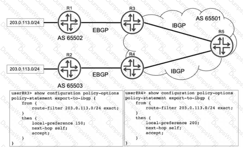
Referring to the exhibit, R1 and R2 are advertising the same prefix 203.0.113.0/24 to R3 and R4 over EBGP. R3 and R4 both advertise this prefix to R5. Which advertisement does R5 choose to install in its routing table?
Options:
The advertisement from R4 is chosen.
The advertisements from both R3 and R4, but R3 is chosen for forwarding.
The advertisement from R3 is chosen.
The advertisements from both R3 and R4, but R4 is chosen for forwarding.
Answer:
AExplanation:
In a Juniper Networks environment, when a router receives multiple BGP paths for the same destination prefix, it utilizes theBGP Path Selection Algorithmto determine the single "best" path to install in the routing table and advertise to other peers. This selection process follows a strict hierarchy of attributes.
According to Juniper Networks technical documentation, the very first attribute evaluated by the BGP process (after ensuring the next hop is reachable) is theLocal Preference. Local preference is a well-known discretionary attribute used to communicate a preference for a specific exit point from the local Autonomous System (AS). A higher local preference value is always preferred over a lower one.
Analyzing the exhibit:
R3receives the prefix from R1 and applies an export policy to its IBGP session that sets thelocal preference to 150.
R4receives the same prefix from R2 and applies an export policy to its IBGP session that sets thelocal preference to 200.
R5receives both of these IBGP updates from R3 and R4.
When R5 runs the best-path algorithm for the 203.0.113.0/24 prefix, it compares the local preference values. Since the path from R4 has a local preference of 200 and the path from R3 has a local preference of 150, R5 immediately selects the path fromR4as the best route. Because BGP is designed to prevent loops and maintain a consistent view, only this single best path is installed as the active route in R5's routing table (inet.0). Options B and D are incorrect because they imply multiple paths are installed for forwarding, which only occurs if specific multipath load-balancing is configured, which is not indicated here.
You are evaluating BGP between two Juniper routers and the BGP session is stuck in the Idle state. What would cause this behavior?
Options:
The BGP hold time is too short.
The BGP group type is set to internal instead of external.
The local AS number is missing.
The peer IP address is incorrect.
Answer:
DExplanation:
In the BGP Finite State Machine (FSM), theIdlestate is the first stage of any BGP connection. When a BGP session is "stuck" in Idle, it typically indicates that the router is unable to even begin the process of establishing a TCP connection with its neighbor. According to Juniper Networks documentation, before BGP can transition to theConnectorActivestates, it must have a valid route to the neighbor's IP address in the routing table and be able to initiate a three-way TCP handshake on port 179.
If thepeer IP address is incorrect(Option D), the router may not have a route to that destination, or it may be attempting to connect to a non-existent or unreachable host. In many Junos configurations, if the underlying IGP (OSPF/IS-IS) or static routing cannot provide reachability to the neighbor address defined in the BGP configuration, the BGP process will remain in the Idle state and periodically retry the connection.
Regarding the other options:
The local AS number is missing (Option C):In Junos, you cannot commit a BGP configuration if the local autonomous system is not defined at either the [edit routing-options] level or within the BGP group itself. The commit check would fail before the session could even attempt to start.
The BGP group type (Option B):Having a mismatch in group type (internal vs. external) usually results in the session reaching theOpenSentorOpenConfirmstate before failing due to an "unacceptable AS" error in the OPEN message.
BGP hold time (Option A):Issues with hold timers or keepalives generally cause a session that is already in theEstablishedstate to drop; they do not prevent the session from leaving the Idle state.
What happens if an IS-IS router receives a link-state PDU with a higher sequence number than the one in its database?
Options:
It ignores the link-state PDU.
It updates its database and floods the link-state PDU.
It sends a CSNP to request confirmation from the source of the link-state PDU.
It resets the adjacency with the source of the link-state PDU.
Answer:
BExplanation:
IS-IS is a link-state protocol that relies on the rapid and consistent flooding ofLink-State PDUs (LSPs)to ensure that every router in an area has an identical view of the topology. To manage the "freshness" of information, IS-IS uses aSequence Number—a 32-bit unsigned integer that increments every time the originating router makes a change to its LSP.
According to Juniper Networks technical documentation, when a router receives an LSP, it performs a comparison between the received LSP and the version it currently holds in itsLink-State Database (LSDB). If the received LSP has ahigher sequence number, the router concludes that this is "newer" and more accurate information. The router will then perform two immediate actions:
Update:It replaces the older LSP in its LSDB with the newly received version.
Flood:It propagates the new LSP to all other neighbors (except the one that sent it) to ensure the entire area converges on the new data.
If the sequence numbers were equal, the router would ignore the incoming PDU as it already has the information. If the received sequence number werelower, the router would conclude its own database is more recent and would actually send its own "newer" version back to the neighbor to bring them up to date (a process called "poisoning" or refreshing the neighbor).Complete Sequence Number PDUs (CSNPs)(Option C) are used during initial database synchronization or periodic checks on broadcast links, but the primary response to a "newer" LSP is immediate database update and flooding.
Exhibit:
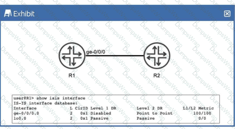
Referring to the exhibit, R1 and R2 are configured to run IS-IS. The IS-IS adjacency between R1 and R2 is up. What does the output of the show isis interface command tell you about R1?
Options:
R1 is not configured to use wide metrics.
R1 only forms a Level 2 adjacency with R2.
R1 advertises a Level 1 metric of 100 and a Level 2 metric of 100 toward R2 in its link-state PDU.
R1 sends Level 1 hello PDUs to R2.
Answer:
BExplanation:
In theIS-IS (Intermediate System to Intermediate System)protocol as implemented in Junos OS, routers can operate at two hierarchical levels:Level 1 (L1)for intra-area routing andLevel 2 (L2)for inter-area backbone routing. By default, a Juniper router and its interfaces are configured to act asLevel 1/2, meaning they will attempt to form adjacencies at both levels simultaneously.
According to Juniper Networks technical documentation, the show isis interface command provides a granular view of how the protocol is interacting with specific local links. In the provided exhibit, we must examine theL (Level)column and theDR (Designated Router)status columns to understand R1's operational state.
Level Configuration:Under the L column for both the physical interface ge-0/0/0.0 and the loopback lo0.0, the value is strictly2. This indicates that these interfaces have been explicitly configured to operate only at Level 2.
Adjacency Capabilities:For the interface ge-0/0/0.0, the Level 1 DR field is marked asDisabled. This confirms that R1 is not participating in Level 1 operations on this link; it will not transmit Level 1 Hello PDUs, nor will it listen for them. Consequently, R1 is incapable of forming a Level 1 adjacency with R2 on this segment.
Metric Implications:The exhibit shows an L1/L2 Metric of100/100. In Junos, "narrow" metrics (the default) are limited to a maximum value of 63 per interface. A metric of 100 indicates thatwide metrics(wide-metrics-only) have been enabled. Therefore, option A is incorrect because the routerisusing wide metrics.
Since the prompt states the adjacency is "up," and the interface is restricted to Level 2, we can conclude thatR1 only forms a Level 2 adjacency with R2 (Option B). Even though an L1 metric of 100 is displayed in the table as a configured value, it is not actually "advertised" in a Link-State PDU because the Level 1 protocol is disabled on that interface.
You are a network architect designing a brand new network. You want to deploy RSVP LSPs in this network. You are currently in the process of choosing whether to run OSPF or IS-IS as your interior gateway protocol. In this scenario, which two statements are correct about IGP traffic engineering extensions in an RSVP network? (Choose two.)
Options:
You must explicitly configure IS-IS to carry traffic engineering extensions.
In OSPF, traffic engineering extensions are enabled by default.
You must explicitly configure OSPF to carry traffic engineering extensions.
In IS-IS, traffic engineering extensions are enabled by default.
Answer:
C, DExplanation:
In a Juniper Networks environment, deployingRSVP-signaled LSPsrequires a functionalTraffic Engineering Database (TED). This database is populated by the Interior Gateway Protocol (IGP) using specific extensions that carry link-state information beyond simple reachability, such as available bandwidth, administrative groups (link coloring), and Maximum Reservable Bandwidth.
The behavior of these extensions differs betweenOSPFandIS-ISin Junos OS:
OSPF (Option C):By default, OSPF is a "pure" routing protocol. To support RSVP-TE, it must carry Opaque LSAs (Type 10). According to Juniper documentation, you mustexplicitly configuretraffic engineering within the OSPF protocol hierarchy using the set protocols ospf traffic-engineering command. Without this command, OSPF will not flood the TE information required by the Constrained Shortest Path First (CSPF) algorithm, and LSPs will fail to establish.
IS-IS (Option D):IS-IS was designed to be extensible through the use of TLVs (Type, Length, Value). In Junos OS,IS-IS traffic engineering extensions are enabled by defaultonce the protocol is active. As soon as you enable IS-IS on an interface, it begins to advertise the wide metrics and TE TLVs (like TLV 22 and 135) necessary for building the TED.
This distinction is a common design consideration for network architects. While IS-IS simplifies the rollout of MPLS by having TE enabled "out of the box," OSPF requires that extra configuration step to transition from a standard IGP to a TE-aware protocol.
Which statement about RSVP-signaled LSPs is correct?
Options:
CSPF is not required for LSPs using admin-groups.
CSPF is used to calculate the path for a traffic-engineered LSP.
The paths used by LSPs are always calculated using the SRGB.
The paths used by LSPs are always calculated using the TED.
Answer:
BExplanation:
In a Juniper Networks environment,Resource Reservation Protocol (RSVP)is a signaling protocol used to establish Label-Switched Paths (LSPs). While RSVP handles the actual signaling (requesting labels and reserving bandwidth along a path), it does not inherently know which path to take. This is whereConstrained Shortest Path First (CSPF)comes into play.
CSPFis an advanced version of the Dijkstra algorithm used specifically for traffic engineering. Unlike the standard SPF used by IGPs, which only considers the shortest metric, CSPF takes into account multiple constraints such as available bandwidth, link coloring (administrative groups), and explicit hop requirements. According to Juniper technical documentation, when an LSP is configured, the Ingress router uses CSPF to calculate a loop-free path that satisfies all these constraints before RSVP begins signaling. This is why statementBis the correct description of the operational flow.
StatementDis a common distractor. While CSPF uses theTraffic Engineering Database (TED)to perform its calculations, the path is not "calculated by the TED" itself; the TED is merely the repository of link-state information (provided by OSPF or IS-IS extensions). StatementCrefers to Segment Routing Global Block (SRGB), which is relevant to Segment Routing (SR-TE), not standard RSVP-signaled LSPs. Finally, statementAis incorrect because admin-groups (link coloring) are actually one of the primary constraints thatrequireCSPF to determine a valid path.
Which term describes the router where traffic enters an MPLS label-switched path (LSP)?
Options:
egress router
transit router
penultimate router
ingress router
Answer:
DExplanation:
In the architecture of aLabel-Switched Path (LSP), routers are categorized based on their role in the handling of a specific packet's lifecycle through the MPLS network. Juniper Networks documentation defines these roles clearly:
TheIngress Router (Option D), also known as theIngress Label Edge Router (LER), is the entry point of the LSP. Its primary responsibility is to take an incoming "unlabeled" packet (usually a standard IPv4 or IPv6 packet), perform a route lookup, and determine which LSP the packet should follow. Once determined, the Ingress router performs aPushoperation, where it encapsulates the packet with an MPLS label header and forwards it toward the next hop. This is where the transition from IP-based forwarding to Label-based switching occurs.
To contrast this with the other options:
Transit Router (Option B):These are routers located between the ingress and egress. They performSwapoperations, replacing an incoming label with an outgoing label based on the Label Forwarding Information Base (LFIB).
Egress Router (Option A):This is the "tail-end" of the LSP where the packet exits the MPLS domain and the final label is removed (if it hasn't been removed already by the penultimate hop).
Penultimate Router (Option C):This is the second-to-last router in the path. As discussed in previous questions, it often performs thePopoperation (Penultimate Hop Popping) to remove the transport label before sending the packet to the Egress LER.
Therefore, the router where traffic first "enters" the LSP and receives its initial label is strictly defined as the Ingress router.
You are using EBGP to connect to two upstream peers in the same AS. You want to make one of the links less preferred for traffic entering your network from the peer's AS. Which feature should you use to achieve this goal?
Options:
a route reflector
origin code
AS-path prepending
local preference
Answer:
CExplanation:
In the world of BGP, controllinginbound traffic(traffic entering your network) is significantly more challenging than controlling outbound traffic because it requires influencing a decision made by an external Autonomous System (AS). According to Juniper Networks documentation, when you have multiple links to the same AS or even different ASes, the BGP path selection process is used by the upstream neighbor to decide which path to take to reach your prefixes.
AS-Path Prependingis the standard technique used to make a path appear less attractive to external peers. By artificially lengthening the AS_PATH attribute on the BGP advertisements sent over a specific link, you exploit the BGP best-path algorithm rule that prefers a shorter AS path. When you prepend your own AS number multiple times to the update sent to the "less preferred" peer, that peer’s BGP routers will see a longer path compared to the alternative link and will naturally prefer the shorter, unprepended route.
It is important to distinguish why other options are incorrect for this specific goal:
Local Preference (Option D):This is a well-known discretionary attribute used to influenceoutboundtraffic. It is not advertised to EBGP peers; therefore, your upstream neighbor cannot see your local preference settings.
Origin Code (Option B):While the origin code (IGP, EGP, or Incomplete) is a tie-breaker in the selection process, it is rarely used for traffic engineering and lacks the granular control provided by prepending.
Route Reflector (Option A):This is an Internal BGP (IBGP) scaling mechanism used to reduce the need for a full mesh of peers within an AS; it does not directly influence external path selection by an upstream provider.
Junos OS allows you to easily implement prepending viarouting policiesapplied as an "export" policy to the EBGP neighbor. By using the as-path-prepend action within a policy term, you can selectively degrade a path's attractiveness to manage your inbound bandwidth.