Data Center - Specialist (JNCIS-DC) Questions and Answers
You are trying to deploy a five-stage template to a blueprint as shown in the exhibit. You cannot see your template name in the list of available templates.
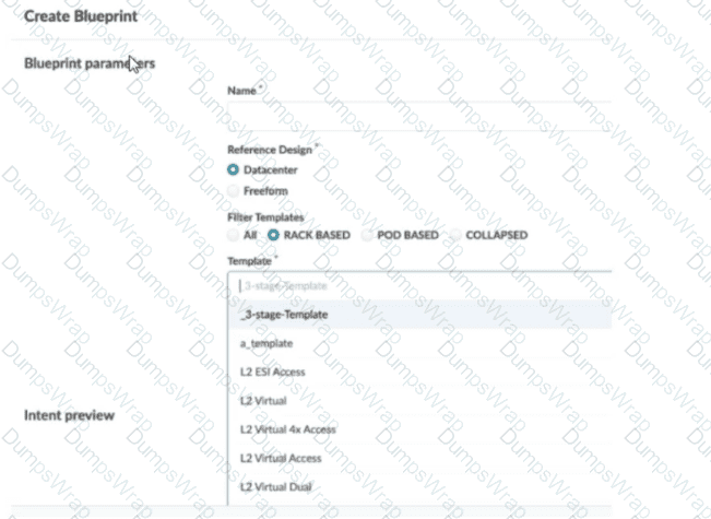
In this scenario, which statement is correct?
Options:
The Collapsed option should be selected.
You must include “five-stage” in the template name for it to appear in the list.
The Pod Based option should be selected.
Only Freeform-type blueprints support five-stage templates.
Answer:
CExplanation:
In Apstra 5.1, templates are organized by template type, and the Create Blueprint screen can filter the template list by those types. A five-stage Clos design in Apstra is represented as a pod-based template (multi-pod fabric with an additional tier such as super-spines to interconnect pods). Because of that, a five-stage template will only appear in the template selector when the Pod Based filter is chosen. If the filter is set to Rack Based or Collapsed, Apstra hides pod-based templates because those types correspond to different topology classes: rack-based aligns with a three-stage leaf–spine pod, while collapsed aligns with a spine-less topology pattern.
This behavior is by design to prevent selecting an incompatible template for the intended topology. The template name itself does not need to contain “five-stage”; Apstra determines its type from how the template was created and stored in the catalog. Also, five-stage templates are not limited to Freeform blueprints—five-stage is a data center fabric topology choice, and it is supported within the data center reference design workflows when the appropriate template type is selected.
So, to make the five-stage template visible and selectable, choose Pod Based in the template filter.
You want to assign resources to your blueprint during the deployment phase. In this scenario, which statement is correct?
Options:
To assign resources in the blueprint, you must have completed the device profile and device assignments.
To assign resources in the blueprint, you must have already created them under global resources.
All resources are created and assigned under the blueprint's Resources tab.
All resources are automatically assigned values from the available resource pools.
Answer:
DExplanation:
In Apstra 5.1, “resources” (such as ASNs, IP addressing, and VNIs) are allocated to blueprint elements using resource pools. The blueprint does not require you to manually craft every individual resource value; instead, Apstra’s workflow is to have you indicate which pool(s) should be used for the blueprint, and then Apstra automatically pulls and assigns the required values. This automation is fundamental to Apstra’s intent-based model: once the blueprint knows which pools to consume, it can deterministically allocate unique values across the fabric and generate consistent Junos configuration for the assigned devices.
Option D best matches this behavior because it reflects the documented mechanism: required resources are automatically pulled from the selected pool(s) and assigned in a fast, bulk transaction. This is what enables repeatable deployments—especially in EVPN-VXLAN data center fabrics—because resource collisions and manual tracking are avoided.
Option A is not the defining prerequisite for resource assignment; device profile and device assignment are important overall build steps, but the correctness of resource assignment is tied to pool selection and availability rather than being strictly gated by those tasks. Option B is incorrect because pools can be created and managed beyond only “global” contexts, and Apstra also supports creating additional pools from within the blueprint when needed. Option C is misleading because resources are governed by pools and allocation, not only by manual creation under a single tab.
Verified Juniper sources (URLs):
You are creating a template using Juniper Apstra. In this scenario, what is a rack-based design compared to a pod-based design?
Options:
A rack-based design allows the operator to select a specified number of downlinked servers, whereas a pod-based design only allows the operator to select fixed “pods” of servers.
A rack-based design refers to a three-stage Clos, and a pod design refers to a five-stage Clos.
A rack-based design is suitable for physical servers, whereas a pod-based design is used for Kubernetes deployments.
A rack-based design connects local servers only, whereas a pod-based design can include virtual workloads in a public cloud.
Answer:
BExplanation:
In Apstra 5.1, templates are used to describe the intended structure of a data center fabric. A rack-based template is used to build the common 3-stage Clos model (spines connected to racks containing leaf/top-of-rack switches and endpoints). In this design, you define the spine logical devices, select one or more rack types, specify rack counts, and define the intended connectivity between spines and racks. This directly models a leaf-spine IP fabric typically used for EVPN-VXLAN in modern data centers.
A pod-based template, by contrast, is explicitly used to build 5-stage Clos networks. In Apstra’s terminology, a pod-based template is essentially a “template of templates”: it combines one or more rack-based templates (each representing a 3-stage pod) and adds an additional superspine layer to interconnect those pods into a larger, scalable fabric. This is the architectural distinction: rack-based describes the leaf-spine pod, while pod-based describes the multi-pod superspine architecture.
For Junos v24.4 EVPN-VXLAN deployments, the difference matters operationally because 5-stage fabrics introduce additional tiers and scaling considerations (for example, superspine connectivity and expanded ECMP domains). Apstra’s template hierarchy ensures consistent intent modeling across both 3-stage and 5-stage topologies without requiring operators to manually redesign the fabric logic each time they scale out.
Verified Juniper sources (URLs):
Exhibit.
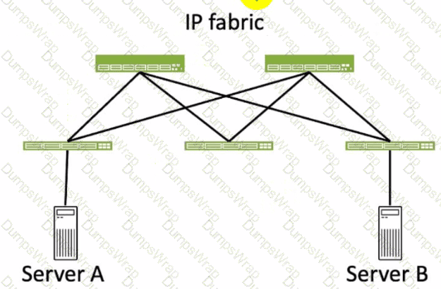
Referring to the exhibit, how many broadcast domains will an Ethernet frame pass through when traversing the IP fabric from Server A to Server B?
Options:
1
4
2
3
Answer:
CExplanation:
Referring to the exhibit, the image shows a simplified diagram of an IP fabric network connecting two servers, labeled as Server A and Server B. The IP fabric is a network architecture that uses a Clos topology to provide high bandwidth, low latency, and scalability for data center networks. The IP fabric consists of spine and leaf devices that use BGP as the routing protocol and VXLAN as the overlay technology1.
A broadcast domain is a logical portion of a network where any device can directly transmit broadcast frames to other devices at the data link layer (OSI Layer 2). A broadcast frame is a frame that has a destination MAC address of all ones (FF:FF:FF:FF:FF:FF), which means that it is intended for all devices in the same broadcast domain. A broadcast domain is usually bounded by a router, which does not forward broadcast frames to other networks2.
In the exhibit, there are two broadcast domains that an Ethernet frame will pass through when traversing the IP fabric from Server A to Server B. The first broadcast domain is the one that contains Server A and the leaf device that it is connected to. The second broadcast domain is the one that contains Server B and the leaf device that it is connected to. The IP fabric itself is not a broadcast domain, because it uses IP routing and VXLAN encapsulation to transport the Ethernet frames over the Layer 3 network. Therefore, the statement C is correct in this scenario.
The following three statements are incorrect in this scenario:
A. 1. This is not true, because there are not one, but two broadcast domains that an Ethernet frame will pass through when traversing the IP fabric from Server A to Server B. The IP fabric itself is not a broadcast domain, because it uses IP routing and VXLAN encapsulation to transport the Ethernet frames over the Layer 3 network.
B. 4. This is not true, because there are not four, but two broadcast domains that an Ethernet frame will pass through when traversing the IP fabric from Server A to Server B. The spine devices and the leaf devices that are not connected to the servers are not part of the broadcast domains, because they use IP routing and VXLAN encapsulation to transport the Ethernet frames over the Layer 3 network.
D. 3. This is not true, because there are not three, but two broadcast domains that an Ethernet frame will pass through when traversing the IP fabric from Server A to Server B. The IP fabric itself is not a broadcast domain, because it uses IP routing and VXLAN encapsulation to transport the Ethernet frames over the Layer 3 network.
You have accessed your deployed blueprint and see the banner shown in the exhibit.

Which two statements are correct in this scenario? (Choose two.)
Options:
Devices must be assigned to profiles.
There are changes that are not active on the fabric.
Resources must be assigned to devices.
There are anomalies that must be addressed.
Answer:
B, DExplanation:
In Apstra 5.1, the top-level blueprint banner uses tab indicators (colored badges) to summarize blueprint status across areas such as Staged, Uncommitted, Active, and Analytics. The presence of an Uncommitted indicator signifies that there are staged modifications that have not yet been committed and therefore are not part of the active, deployed intent. That directly corresponds to the statement that changes exist which are not active on the fabric.
At the same time, the banner shows an Active indicator in an alarm state, which reflects that the running fabric has issues requiring attention—commonly surfaced as anomalies (for example, configuration deviation, interface/link faults, protocol/session issues, or service-impacting conditions). In Apstra’s operational model, these issues appear as anomalies that operators should investigate and remediate to restore compliance and health. Therefore, the statement that there are anomalies that must be addressed is also correct.
The remaining options are not implied by this banner alone. Device profile assignment and resource assignment are build-time tasks, but their absence is not what the Uncommitted/Active alert indicators are specifically communicating here. The banner is highlighting uncommitted intent changes and active anomalies that affect the deployed blueprint state and assurance posture.
Verified Juniper sources (URLs):
Within Managed Devices in the Juniper Apstra Ul, you notice that several devices have the OOS-Quarantined status. The devices cannot be added to any blueprint. Which action would solve this problem?
Options:
Acknowledge the device.
Fix the hardware issues with the quarantined devices.
Install the agent, even though connectivity is established.
Upload a new pristine configuration.
Answer:
AExplanation:
When an agent installation is successful, devices are placed into the Out of Service Quarantined (OOS-QUARANTINED) state using the Juniper Apstra UI. This state means that the device is not yet managed by Apstra and has not been assigned to any blueprint. The device configuration at this point is called Pristine Config. To make the device ready for use in a blueprint, you need to acknowledge the device, which is a manual action that confirms the device identity and ownership. Acknowledging the device changes its status to Out of Service Ready (OOS-READY)12. References:
Managing Devices
AOS Device Configuration Lifecycle
Which type of generic system should you select when adding a new server inside an existing rack type?
Options:
Internal generic
Rack generic
External generic
Embedded generic
Answer:
AExplanation:
In Apstra 5.1, servers that connect to leaf switches are represented as generic systems so Apstra can model links, apply connectivity templates, attach virtual networks, and validate intent. The selection of generic system type depends on whether the endpoint is considered part of the rack’s internal topology or an external attachment. When you add a new server inside an existing rack type, that server is treated as a component of the rack topology (that is, it lives “within” the rack alongside leaf switches and any other rack-internal endpoints). Apstra documentation refers to such systems as internal generic systems.
Internal generic systems are not managed like switches (no full device management), but they are first-class topology objects: they occupy ports on leaf switches, can be tagged with roles, and can be associated with link definitions that drive correct interface intent (LAG vs single link, VLAN tagging, and virtual network association). This modeling is essential in EVPN-VXLAN fabrics because correct endpoint attachment on leaf ports determines VLAN/VNI mapping and the resulting Junos v24.4 configuration rendered by Apstra.
External generic systems, by contrast, represent devices outside the rack topology (often used for external routers, firewalls, or other non-rack-contained endpoints). Because the question explicitly places the server inside an existing rack type, the correct choice is Internal generic.
Verified Juniper sources (URLs):
You are using Juniper Apstra to create security policies that create ACLs on the fabric devices. What are two valid objects that would be used within Apstra in this scenario? (Choose two.)
Options:
Virtual network
Domain name
Routing zone
Application signature
Answer:
A, CExplanation:
In Apstra 5.1, Security Policies express traffic-permit/deny intent between defined fabric endpoints, and Apstra compiles that intent into ACL enforcement on the appropriate switches (for example, on gateway interfaces for east-west segmentation and on border leaf interfaces for north-south controls). The objects you use to define that policy intent must correspond to fabric connectivity constructs that Apstra understands as endpoints in the blueprint’s logical model.
Two such valid objects are Virtual Networks and Routing Zones. A virtual network represents a tenant segment (typically mapped into EVPN-VXLAN constructs such as VNI and associated IRB gateway when L3 is enabled). Policies between virtual networks are a common way to implement micro-segmentation or tier-based segmentation (web/app/db) within the same tenant boundary. A routing zone represents the L3 tenancy boundary (mapped to a VRF) and can be used to group and control connectivity at the tenant level, especially where policy needs to be expressed for aggregated tenant domains or for controls involving external connectivity.
“Domain name” and “application signature” are not endpoint objects for Apstra Security Policies in this context. They may exist in other security ecosystems, but Apstra’s security intent model for ACL generation is based on topology and blueprint objects (routing zones, virtual networks, and endpoint definitions), which can then be rendered into Junos v24.4 firewall filter–style enforcement on the fabric devices.
Verified Juniper sources (URLs):
Which two statements are correct about a Juniper Apstra server? (Choose two.)
Options:
The Juniper Apstra server uses Layer 2 to communicate with managed devices.
The Juniper Apstra server requires one network adapter connection for each managed device.
The Juniper Apstra server uses Layer 3 to communicate with managed devices.
The Juniper Apstra server requires a single network adapter.
Answer:
C, DExplanation:
Apstra manages devices using IP connectivity over the management network, which is a Layer 3 relationship. Whether you are using on-box agents or off-box agents, the controller (or cluster) communicates with the fabric devices using IP reachability (for example, to exchange management traffic, retrieve discovery state, collect telemetry, and push configuration). This is why Layer 2 adjacency is not required between the Apstra server and the managed switches; the essential requirement is routable IP connectivity and appropriate access (credentials/agent connectivity) to the device management interfaces.
From a platform perspective, Apstra does not need a dedicated physical NIC per managed device. Instead, the server/VM requires connectivity to the management network through a single network adapter, and that interface can route to all managed devices. In a typical data center deployment, the Apstra controller VM sits on a management VLAN/subnet and reaches the entire fabric through routed management. This scales operationally: adding devices does not require adding additional server NICs; it only requires IP reachability and capacity planning for telemetry and agent workloads. Thus, the correct statements are that Apstra uses Layer 3 to communicate with managed devices and that it requires a single network adapter for that management connectivity model.
Which two actions are required during Juniper Apstra's deploy phase? (Choose two.)
Options:
Assign device profiles to the blueprint.
Assign user roles to the blueprint.
Assign interlace maps to the blueprint.
Assign resources to the blueprint.
Answer:
A, DExplanation:
The deploy phase is the final step in the Juniper Apstra data center fabric design and deployment process. In this phase, you apply the Apstra-rendered configuration to the devices and verify the intent of the blueprint. Based on the web search results, we can infer the following actions are required during the deploy phase12:
Assign device profiles to the blueprint. This action associates a specific vendor model to each logical device in the blueprint. Device profiles contain extensive hardware model details, such as form factor, ASIC, CPU, RAM, ECMP limit, and supported features. Device profiles also define how configuration is generated, how telemetry commands are rendered, and how configuration is deployed on a device. Device profiles enable the Apstra system to render and deploy the configuration according to the Apstra Reference Design34.
Assign resources to the blueprint. This action allocates the physical devices, IP addresses, VLANs, and ASNs to the logical devices, networks, and routing zones in the blueprint. Resources can be assigned manually or automatically by the Apstra system. Assigning resources ensures that the blueprint has all the necessary elements to generate the configuration and deploy the fabric5 .
Assign user roles to the blueprint. This action is not required during the deploy phase. User roles are defined at the system level, not at the blueprint level. User roles determine the permissions and access levels of different users in the Apstra system. User roles can be system-defined or custom-defined .
Assign interface maps to the blueprint. This action is not required during the deploy phase. Interface maps are defined at the design phase, not at the deploy phase. Interface maps are objects that map the logical interfaces of a logical device to the physical interfaces of a device profile. Interface maps enable the Apstra system to generate the correct interface configuration for each device in the fabric . References:
Deploy
Deploy Device
Device Profiles
Juniper Device Profiles
Resources
What does VXLAN use to uniquely label and identify broadcast domains?
Options:
VLAN ID
Agent Circuit Identifier (ACI)
Virtual Network Identifier (VNI)
End System Identifier (ESI)
Answer:
CExplanation:
In a VXLAN overlay, each Layer 2 broadcast domain (the logical equivalent of a VLAN/bridge domain) is identified by a 24-bit VXLAN Network Identifier (VNI) carried in the VXLAN header. This VNI is what allows the overlay to scale far beyond traditional VLAN space (12-bit VLAN IDs), enabling up to ~16 million distinct segments. In an EVPN-VXLAN data center fabric, Junos v24.4 leaf switches operate as VTEPs and map local bridge domains (often associated with VLANs on server-facing ports) to a VNI. When traffic is sent across the routed underlay, the leaf encapsulates Ethernet frames into VXLAN packets and inserts the VNI so the receiving VTEP can place the frame into the correct broadcast domain on decapsulation.
Apstra 5.1 abstracts this mapping through virtual networks and resource allocation: when you define a VXLAN-based virtual network, Apstra allocates a VNI from the appropriate pool and consistently programs the necessary constructs on all participating leaves. The key point is that VNI is the unique identifier in the VXLAN data plane used to label the broadcast domain across the IP fabric; VLAN IDs may exist locally at the edge for tagging, but the globally significant overlay identifier is the VNI.
Verified Juniper sources (URLs):
What is the primary reason for creating an Apstra worker node?
Options:
To support more than one blueprint
To create a space for storing event logs
To run Zero Touch Provisioning (ZTP)
To offload off-box agents and Intent-Based Analytics (IBA)
Answer:
DExplanation:
In Apstra 5.1, the worker node’s primary purpose is to add scalable runtime capacity to an Apstra cluster by hosting off-box services that would otherwise consume resources on the controller. Specifically, worker nodes run containerized services such as off-box device agents (used to communicate with and manage devices) and Intent-Based Analytics (IBA) components (such as probes and analytics-related services). This design keeps the controller node focused on cluster management and control-plane functions (API handling, cluster-wide state, blueprint control workflows), while shifting resource-intensive operational services to worker nodes.
As your fabric grows—more switches, more telemetry, more devices requiring agent connectivity—CPU and memory demand increases notably, especially when IBA is enabled. Adding worker nodes allows you to scale those container workloads horizontally without redesigning the fabric or reducing analytics coverage. In a Juniper data center built on EVPN-VXLAN with Junos v24.4 leaf-spine roles, this separation helps ensure that Apstra can continuously validate intent, process streaming telemetry, and maintain device communications reliably at scale. Worker nodes therefore exist primarily to offload and scale operational agents and IBA services, improving performance and resilience for larger deployments.
You are creating a new security policy using Juniper Apstra.
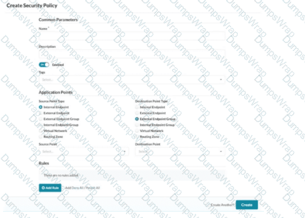
Referring to the exhibit, which application point should you select to allow or deny traffic to or from a particular VRF?
Options:
Routing Zone
External Endpoint
Internal Endpoint
Virtual Network
Answer:
AExplanation:
In Apstra 5.1, multitenancy is modeled using routing zones, which map directly to the network operating system concept of a VRF. A VRF is an isolated Layer 3 routing instance with its own routing table and forwarding context, and Apstra’s routing zone is the intent-based abstraction used to define and manage that isolation consistently across the fabric. Therefore, if your goal is to allow or deny traffic to or from a particular VRF, you must select Routing Zone as the security policy application point.
This choice enables you to express policy at the tenant boundary (VRF boundary) rather than at a single segment boundary. In EVPN-VXLAN data center fabrics, a tenant VRF commonly contains multiple virtual networks (VXLAN segments) and their associated IRB gateways on the leaf switches. Applying policy at the routing-zone level allows Apstra to compile intent and deploy enforcement consistently where traffic enters or exits that VRF context—typically as ACL constructs rendered as Junos firewall filters on the appropriate interfaces (for example, IRB interfaces for east-west controls or border interfaces for north-south controls).
By contrast, selecting Virtual Network targets a single segment (not the whole VRF), and Internal/External Endpoint targets specific endpoints or endpoint groups rather than the VRF-wide policy boundary. Hence, Routing Zone is the correct application point when policy scope is the VRF.
What are two types of virtual networks defined inside Juniper Apstra software? (Choose two.)
Options:
VLAN
L3 VPN
VXLAN
L2 VPN
Answer:
A, CExplanation:
In Apstra 5.1, a Virtual Network (VN) is Apstra’s abstraction for a Layer 2 forwarding domain that groups endpoints into a logical segment across the fabric. Apstra defines virtual networks as being constructed using either VLANs or VXLANs. A VLAN-based VN represents a Layer 2 domain identified by a VLAN ID and is typically used where you want traditional VLAN semantics (often in smaller environments, migration scenarios, or designs where an overlay is not required). A VXLAN-based VN represents the same Layer 2 intent but uses a VXLAN VNI for scalable overlay segmentation, which is the common approach in EVPN-VXLAN data center fabrics.
In an IP fabric architecture, VXLAN provides encapsulation to carry tenant segments over the routed underlay, while EVPN provides the control-plane signaling for MAC/IP reachability. Junos v24.4 leaf devices act as VTEPs, mapping local VLANs/bridge-domains to VNIs and participating in EVPN for advertisement and convergence. Apstra’s VN construct allows you to create the segment once (as VLAN or VXLAN type), then consistently attach it to racks, ports, and endpoints through intent-driven workflows (such as connectivity templates and virtual network assignments).
“L2 VPN” and “L3 VPN” are service provider terms and are not the VN “types” in Apstra’s data center reference design. In Apstra, tenant L3 separation is modeled by routing zones (VRFs), while the VN itself is specifically either VLAN-based or VXLAN-based.
Verified Juniper sources (URLs):
Juniper Apstra provides five different predefined user roles. Given this information, what is the main difference between the administrator and the user role?
Options:
The user role can only be assigned to specific blueprints.
The user role can make changes to any other role.
The user role cannot make any changes to other user types.
The user role can only make changes to the view role.
Answer:
CExplanation:
Apstra role-based access control separates fabric operations from identity and authorization administration. The administrator role includes full permissions, including the ability to manage users and roles (for example, creating users, assigning permissions, and creating/cloning/editing custom roles where allowed). This enables administrators to govern who can access the system and what they are permitted to change across all blueprints and system settings.
The user role, in contrast, is designed for day-to-day fabric work: viewing and editing supported blueprint elements and operational objects within the scope permitted by the role, but not administering other users’ access or modifying the role structure itself. In other words, a user can work on the network intent and operations, but cannot elevate privileges, change other users’ roles, or otherwise manage user/role administration unless explicitly granted additional permissions through custom roles.
That makes option C the correct statement: the user role cannot make changes to other user types (that is, it lacks the permissions needed to administer identities/roles). Options A, B, and D do not reflect Apstra’s RBAC model: roles are not primarily constrained “per blueprint” in that way, and users are not intended to modify other roles—those are administrator-level capabilities.
Verified Juniper sources (URLs):
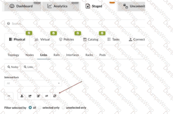
What does clicking the indicated icon shown in the exhibit accomplish?
Options:
It refreshes the screen.
It fetches the discovered Link Layer Discovery Protocol (LLDP) data.
It erases the entire cable map to start over.
It changes the speed of existing links.
Answer:
BExplanation:
In Apstra 5.1, the Staged > Physical > Links workspace is where you build and validate the cabling (link) intent for the fabric before committing changes. During deployment and day-0/1 build, Apstra can leverage LLDP neighbor discovery from the connected devices to accelerate and validate the cabling map. The indicated toolbar icon in the Links view is used to fetch discovered LLDP data from the devices so Apstra can compare the discovered neighbor relationships with the intended topology and, depending on workflow, help populate or validate link endpoints.
This is particularly important in leaf-spine IP fabrics because correct physical connectivity underpins the entire underlay—interface states, point-to-point addressing, and BGP sessions. In an EVPN-VXLAN design running Junos v24.4, broken or mis-cabled links quickly manifest as missing underlay adjacencies and failed EVPN control-plane signaling. Pulling LLDP discovery into Apstra helps you identify mismatches early (wrong neighbor, wrong port, missing neighbor) and reduces manual cabling errors.
This action is not merely a UI refresh, it does not wipe the cable map, and it does not modify link speeds. Its operational purpose is to import discovered LLDP neighbor information into the blueprint’s physical link view so Apstra can assist with accurate topology validation and deployment readiness.
Which element of an intent-based analytics (IBA) probe is used to specify the database objects to which the probe will apply?
Options:
Reference design schema
Graph query
Database nodes
Node-edge relationship
Answer:
BExplanation:
In Apstra 5.1, Intent-Based Analytics (IBA) is built on Apstra’s graph-based source of truth, where devices, interfaces, links, routing constructs, and services are represented as nodes with relationships. An IBA probe is effectively a processing pipeline (a directed acyclic graph of stages and processors) that ingests telemetry and then performs calculations, aggregations, and anomaly detection. To make any of that work, the probe must first determine which specific objects in the graph—for example, which leaf switches, which uplinks, which BGP sessions, or which interface counters—should be included in the analysis.
The probe element that selects those objects is the graph query. A graph query is evaluated against Apstra’s graph database to return a set of matching nodes/relationships; those query results then become the scope for ingestion and subsequent processing. In other words, the graph query defines “apply this probe to these devices/interfaces/sessions,” and it also provides the context used to bind telemetry identities (key-value pairs describing the metric source) to the correct logical objects in the blueprint. This is why Apstra documentation describes early probe processors producing outputs whose cardinality aligns with the number of results returned by the specified graph query(s). Without a graph query, the probe would not have a deterministic, intent-aligned target set for analytics, and the same probe definition could not be reliably reused across fabrics or blueprints.
You are allowed to assign tags for which three objects? (Choose three.)
Options:
Virtual networks
Interfaces
Generic systems
Property sets
Device profiles
Answer:
A, B, CExplanation:
In Apstra, tags are an intent-level metadata mechanism used to classify objects and drive automation and reuse. Within a data center blueprint, Apstra supports tagging multiple blueprint objects so operators can apply configuration or policy logic conditionally (for example, applying a connectivity template or a configlet based on a tag match). In this scenario, three valid taggable objects are virtual networks, interfaces, and generic systems.
Virtual network tagging is supported directly from the blueprint’s virtual network table, enabling you to label virtual networks (such as “finance,” “pci,” or “dev”) and then reference those tags elsewhere in blueprint operations and policy application. Interface tagging is also explicitly supported in the blueprint, allowing you to assign tags to switch interfaces and use those tags to control how templates, assignments, or other intent-driven operations apply to those ports. Finally, generic systems (which are modeled endpoint systems such as servers or external routers represented as “systems” in the blueprint) can be tagged so that downstream intent logic can distinguish system roles and apply the correct operations consistently across expansions and changes.
By contrast, property sets are structured data objects used for variable substitution and probe/configlet parameterization, not a primary target for operational tagging in the blueprint UI; and device profiles are catalog artifacts describing hardware/NOS compatibility rather than blueprint objects typically tagged for intent application.
Verified Juniper sources (URLs):
You are using Juniper Apstra to create logical devices and interface maps. You use them in three different rack types. You then modify the logical devices to support the required increased interface speeds and receive an error message when updating the logical devices.
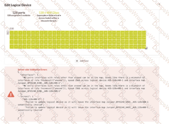
Referring to the exhibit, which action is needed to remove the error?
Options:
Remove any templates that reference the logical device.
Remove any interface maps that reference the logical device.
Remove any racks that reference the logical device.
Remove any templates, racks, and interface maps that reference the logical device.
Answer:
DExplanation:
In Apstra 5.1, a logical device defines the abstract port layout and capabilities (including supported speeds), while an interface map binds that abstract port layout to the real, vendor-specific front-panel ports. Rack types then consume logical devices and interface maps to model the rack’s leaf/superspine roles. Once a logical device is referenced by interface maps and used inside rack types (and potentially templates that instantiate those rack types), Apstra treats the combination as a consistent contract: port counts, roles, and speeds must remain semantically valid for every object that depends on it.
The exhibit’s validation error indicates that after changing interface speeds on the logical device, the existing interface map(s) and their usage in rack types no longer match the logical device definition (for example, the map expects certain ports/speeds/roles, but the updated logical device would leave the map invalid). Because the logical device is being consumed in multiple places, the safest and required way to remove the error is to remove all dependencies—templates (if they reference the rack types), rack types, and interface maps—so Apstra can accept the new logical device definition without violating existing mappings. After updating the logical device, you then recreate or update the interface maps and re-associate them with the rack types/templates so the entire chain remains consistent under the new speed requirements.