Nokia Optical Networking Fundamentals Questions and Answers
Which of the following statements about coherent transmission in WDM technology is TRUE?
Options:
Coherent systems need carrier phase information at the receiver.
Only multi-mode fibers can be used with coherent transmissions.
The channel allocation is flexible, according to the channel size of the signals.
At each receiver, a dispersion compensation unit is often necessary, depending on the fiber length.
Answer:
AExplanation:
Comprehensive and Detailed Explanation From Nokia Optical Networking Fundamentals:
Coherent transmission represents a massive leap in optical technology, moving beyond simple "on-off keying" (Intensity Modulation) to more complex modulation formats like QPSK or 16-QAM. A fundamental requirement of a coherent receiver is the ability to recover and track thecarrier phase informationof the incoming signal. This is achieved by using aLocal Oscillator (LO)laser at the receiver that interferes with the incoming signal, allowing the receiver to extract phase and polarization data.
Unlike legacy 10G direct-detection systems, coherent systems (like Nokia’s PSE-V engine) performDigital Signal Processing (DSP)to electronically compensate for impairments. This makesOption D false, as physical Dispersion Compensation Modules (DCMs) are actually detrimental and usually removed in coherent networks.Option Bis incorrect as coherent transmission is designed for Single-Mode Fiber (SMF).Option Crefers to Flex-grid technology; while coherent signals often use Flex-grid, thedefiningcharacteristic of coherent technology is the phase-sensitive detection at the receiver.
Which of the following statements about the ODUk unit is TRUE?
Options:
The ODUk contains the FEC.
The ODUk is the basic payload that can be electronically groomed and switched in the OTN network.
The ODUk is processed at an optical level.
The ODUk is the first container in which the client signal is inserted.
Answer:
BExplanation:
Comprehensive and Detailed Explanation From Nokia Optical Networking Fundamentals:
In theOptical Transport Network (OTN)hierarchy, theODUk (Optical Data Unit of order k)is the fundamental unit for electronic grooming and switching. Unlike the OTUk layer, which is tied to a specific physical optical interface and includes theForward Error Correction (FEC), the ODUk layer is "path-oriented." This means that in a switched WDM system like the Nokia 1830 PSS-24x, the ODUk containers can be switched across a backplane from one line card to another without needing to deconstruct the entire optical signal.
To clarify the other options:Option Ais false because FEC is part of theOTUk(Transport Unit) layer.Option Cis false because ODUk processing is entirelyelectrical(O-E-O must occur to access the ODUk overhead).Option Dis false because theOPU (Optical Payload Unit)is actually the "first" container where the client signal is mapped; the ODUk then wraps around the OPU to add path-level monitoring and maintenance signals. Therefore, the ODUk acts as the "virtual container" that allows the network to manage services end-to-end across multiple optical spans.
What is the meaning of demand in EPT?
Options:
Demand refers to the amount of OTN interfaces within a single network element.
Demand refers to the required capacity of a single network element in terms of bandwidth.
Demand refers to the required number of trails to be automatically created to meet design requirements.
Demand refers to one or more client signal.
Answer:
DExplanation:
Comprehensive and Detailed Explanation From Nokia Optical Networking Fundamentals:
In the context of theNokia 1830 Engineering and Planning Tool (EPT)—now known asWaveSuite Planner (WS-P)—aDemandis a fundamental planning object that represents the customer’s traffic requirement between two or more nodes. Specifically, it refers toone or more client signalsthat need to be transported across the optical network. When a user defines a demand in EPT, they specify the source and destination nodes, the type of client service (e.g., 10GE, 100GE, or STM-64), the quantity of these services, and the required protection level (e.g., Unprotected, 1+1, or O-SNCP).
The tool uses these defined demands to calculate the most efficient optical path, select the appropriate hardware (transponders and muxponders), and determine the necessary wavelength assignments. While a demand eventually results in the creation of optical trails and utilizes network element capacity, the term itself strictly refers to theinput traffic requirementor the client signal(s) that the network is being designed to carry. Without defining demands, the planning tool cannot generate a Bill of Materials (BOM) or perform power balancing simulations, as it wouldn't know the traffic load the physical infrastructure must support.
What does it take to get connected to the NSP platform?
Options:
A browser and the NSP IP address; and from the landing page, the NSP application should be downloaded and launched.
A browser and the NSP IP address. Then, a browser plugin needs to be installed and the laptop rebooted before the NSP can be correctly reached.
A browser, the NSP IP address, and the credentials to access the web-based interface (WebUI).
The NSP package should be downloaded from the Nokia website and properly licensed for the specific workstation to be used.
Answer:
CExplanation:
To get connected to the Nokia Service Platform (NSP) platform, you need a browser and the NSP IP address. Then, you need the credentials to access the web-based interface (WebUI) for the NSP platform. Once you have these, you can access the NSP platform from a web browser.
In which window(s) does the attenuation reach its minimum peak?
Options:
First window (850 nm)
Second window (1300 nm)
Third window (1550 nm)
Both first and second windows
Answer:
CExplanation:
The third window (1550 nm) is where the attenuation reaches its minimum peak. This is because the materials used in fiber optic cables have minimal absorption in this wavelength range. The first and second windows (850 nm and 1300 nm respectively) have higher attenuation due to the materials used in the fiber optic cables.
Which statement is correct about the NFM-T network map?
Options:
It automatically represents all nodes grouped by the location string assigned during the NE creation.
It represents all supervised nodes grouped by alarm status (with a different color).
It allows context sensitive navigation and represents nodes and related physical connections with different colors. depending on the active alarms.
It allows the graphical visualization of the services deployed in the network with the details of the boards involved in the service.
Answer:
CExplanation:
The NFM-T network map provides a graphical view of the network with different colors used to represent each node, physical connection, and active alarm. It allows the user to quickly identify any issues in the network and provides context sensitive navigation.
How can a mesh network be upgraded so that more services can be transported?
Options:
Configuring new WSS cards is the most effective way to give flexibility and network bandwidth to an existing mesh network.
The Protection and Restoration Combined (PRC) mechanism can enable more bandwidth but only for the protected services.
Upgrading the network to coherent transmission is the only effective way to enable more bandwidth to the existing mesh network.
Upgrading link capacity and/or installing new links provides more bandwidth to the existing mesh network.
Answer:
DExplanation:
Comprehensive and Detailed Explanation From Nokia Optical Networking Fundamentals:
While technologies like WSS (Wavelength Selective Switches) and coherent transmission (100G/200G/400G+) significantly improve the efficiency and reach of a network, the most direct way to increase the total transportable volume of services in a mesh topology is toupgrade link capacityorinstall new physical links. In Nokia optical planning, upgrading link capacity typically involves moving from a lower-rate system (like 10G) to a higher-rate system (like 100G or 400G) or increasing the number of available wavelengths by expanding from a 40-channel to an 80-channel or 96-channel C-band system.
Adding new links (new fiber spans) creates more degrees in the mesh, providing more paths for traffic and increasing the overall aggregate bandwidth of the network.Option Arefers to flexibility (ROADM functionality) rather than raw capacity.Option B(PRC) relates to survivability and availability, not capacity expansion. WhileOption C(coherent transmission) is a powerful method for increasing capacity per wavelength, it is not the "only" way, as adding more fiber (spatial multiplexing) or more channels (spectral density) are also primary methods for scaling a mesh network to handle more services.
Which macro steps can be executed via CPB?
Options:
Node creation, systems validation and system provisioning
Power adjustment and generation of the system loss report
Systems validation, system provisioning, power adjustment
Node supervision, system validation and system provision
Answer:
AExplanation:
Node creation, systems validation and system provisioning. The CPB (Commissioning Parameter Builder) application is used to generate commissioning files for a Nokia 1830 Photonic Service Switch (PSS-1) and can be used to create new nodes, validate the system configuration, and provision the system with the appropriate settings and parameters. Power adjustment and generation of system loss report are not related to CPB.
Which of the following statements is true about chromatic dispersion (CD)?
Options:
Different channels have different bandwidth and this causes different CD performances.
The fiber attenuation changes along the fiber, and when the light crosses these differences the CD takes place.
Different wavelengths propagate at different speeds within the same media and therefore different colors travel in the fiber with different speed.
The fiber attenuation introduces inter-channel interference.
Answer:
CExplanation:
Different wavelengths propagate at different speeds within the same media and therefore different colors travel in the fiber with different speed. This phenomenon is known as chromatic dispersion and causes light to spread out as it travels through the fiber over distance, leading to signal attenuation and distortion. The fiber attenuation does not introduce inter-channel interference, but it can cause attenuation of the signal. Different channels have different bandwidths, but this does not affect CD performance.
Where can the user set the long-haul WT decoder parameter, when designing a network with EPT?
Options:
In the network parameters
In the optimization parameters
In the NE parameters
In the audit menu
Answer:
CExplanation:
The long-haul WT decoder parameter can be set in the NE parameters when designing a network with EPT. This parameter is used to adjust the sensitivity of the decoder and can help to improve the accuracy of the measurements for long-haul WTs.
The Network Element (NE) parameters in EPT (Element Planning Tool) are used to configure various settings and options for the network elements in the network. The long-haul WT decoder parameter is one such setting that can be configured in the NE parameters section. The user can access the NE parameters by navigating to the NE Parameters menu within the EPT interface. The user can then select the appropriate network element and modify the settings as needed. This information can be found in the Nokia guide for EPT.
Where is the OPS card equipped to provide the optical channel protection?
Options:
Between the transponder and the amplifiers
Between the filters and the amplifiers
Before the transponder, on the client side, towards the external device
Between the transponder and the filter
Answer:
AExplanation:
According to the Nokia's 1830 Photonic Service Switch (PSS) product documentation, the Optical Protection Switching (OPS) card is equipped in the transponder and is responsible for providing optical channel protection between the transponder and the amplifiers. The OPS card monitors the optical signal and switches to a pre-configured protection path in case of signal degradation or loss.
WDM allows transmission systems to:
Options:
Transport multiple signals transparently, onto several wavelengths, all together over one single fiber
Increase the bit rate of each client signal by spreading it over multiple wavelengths
Share a single signal among multiple fibers doing load balancing, and thus increasing the reliability of the optical transmission
Allocate different signals to different time slots
Answer:
AExplanation:
WDM (Wavelength Division Multiplexing) allows transmission systems to transport multiple signals transparently, onto several wavelengths, all together over one single fiber. This allows for increased capacity, as many different signals can be transmitted at the same time and along the same fiber. Other advantages include improved signal integrity and reduced signal attenuation.
Which of the following statements best describes the definition of PCT?
Options:
A tool supporting nodes' automatic provisioning on NFM-T.
A tool to validate internal fiber connectivity on CDC-F 2.0 nodes.
A tool supporting zero-touch power management on PSS-32 equipment.
A tool supporting external links autodiscovery on NFM-T.
Answer:
BExplanation:
Comprehensive and Detailed Explanation From Nokia Optical Networking Fundamentals:
ThePhotonic Connectivity Tool (PCT)is a specialized utility within the Nokia 1830 PSS ecosystem designed specifically for modern, complex node architectures. As networks evolved towardCDC-F (Colorless, Directionless, Contentionless with Flex-grid), the internal fiber cabling within a single node became significantly more complex, involving numerous connections between WSS modules, Multicast Switches (MCS), and amplifiers.
The PCT is used tovalidate internal fiber connectivity, ensuring that the physical "patching" matches the intended design before service provisioning begins. It leverages the OSRP (Optical Signal Routing Protocol) or specialized control plane mechanisms to verify that light can flow through the internal cross-connects as expected. This tool is essential for reducing human error during the installation of high-degree ROADM sites, where dozens of internal fibers must be correctly mapped to ensure the "Directionless" and "Contentionless" features function without blocking.
Which use case is most suitable for the deployment of a star topology?
Options:
Access networks, for collecting traffic towards the main central node
ASON networks, to protect traffic via GMPL5 protocols
Backbone networks, for supporting protection routes
SNCP-protected links
Answer:
AExplanation:
A star topology is a network design where all devices are connected to a central hub, which acts as a central point of control and management for the network. This type of topology is commonly used in access networks, where a central node is used to aggregate traffic from multiple users or devices, and then forward it to the core network. This design allows for efficient use of resources and easy management of the network.
With reference to the image, where is the OPS card placed to provide the OMSP protection?
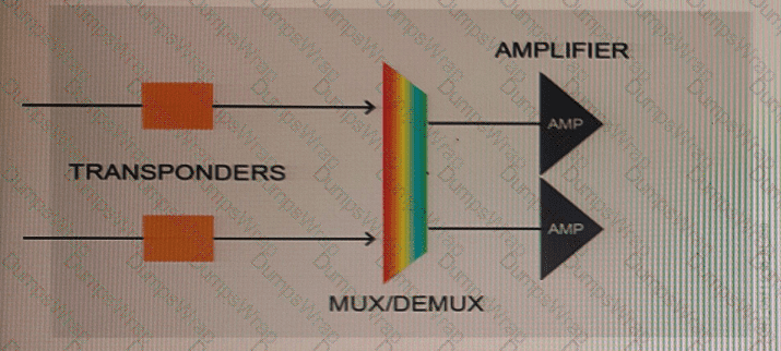
Options:
After the amplifiers
Between the mux/demux and the amplifier
Between the transponders and the mux/demux
Before the transponder, on the client side, towards the external device
Answer:
DWhich of the following statements about Wavelength Tracker monitoring points in CDC-F architecture is TRUE?
Options:
Wavelength Tracker monitoring points are settled on ITL mux interfaces and on OTs line interfaces.
Wavelength Tracker monitoring points are settled on IRDMxx line interfaces only.
Wavelength Tracker monitoring points are settled on IRDMxx line interfaces and on CWR CLS interfaces.
Wavelength Tracker monitoring points are settled on IRDMxx and OTs line interfaces.
Answer:
CExplanation:
Comprehensive and Detailed Explanation From Nokia Optical Networking Fundamentals:
In aCDC-F (Colorless, Directionless, Contentionless, Flex-grid)architecture, the placement of monitoring points is vital for end-to-end visibility of wavelengths. Nokia's Wavelength Tracker technology relies on these points to detect the unique "keys" or signatures associated with each wavelength. In a CDC-F node, the primary monitoring points are located on theIRDMxx(Intelligent Reconfigurable Demultiplexer/Mux) line interfaces and theCWR(Colorless Wavelength Router)CLS(Colorless) interfaces.
TheIRDMmonitoring points allow the system to verify the power and presence of wavelengths as they enter or leave the fiber spans (degrees). TheCWR CLSmonitoring points are critical because they provide visibility at the "Colorless" add/drop stage. By having monitoring at both locations, theWaveSuite Network Operations Center (WS-NOC)can pinpoint exactly where a signal loss or power degradation is occurring—whether it's in the external fiber plant or within the internal colorless switching fabric of the ROADM. This granular visibility is what allows Nokia's "Power Management" to automate balancing across complex mesh topologies.
What is the function of a pre-amplifier in an optical network?
Options:
Through the pre-amplifier, the optical signal is amplified at the receiver side after it travels along the fiber from another node.
Through the pre-amplifier, the optical signal is amplified at the transmitter side before it is sent to the line span.
Through the pre-amplifier, the optical signal is amplified both the receiver side and at the transmitter side.
Through the pre-amplifier, the optical signal is amplified within the node internally to recover internal losses due, for instance, to cascaded filters.
Answer:
BExplanation:
A pre-amplifier is an optical amplifier that is used to boost the power of the received optical signal before it is detected by the receiver in an optical communication system. This is done to overcome the loss of power that occurs as the signal travels through the optical fiber and to ensure that the receiver can detect the signal. The pre-amplification stage is typically located close to the receiver in order to minimize the distance that the signal has to travel between the amplifier and the receiver, which helps to reduce the noise and distortion in the signal.